
Die-cutting machine split type electric cabinet box installing structure with high shock resistance

A die-cutting machine and shock-resistant technology, applied in the direction of connecting components, mechanical equipment, pins, etc., can solve the problems of falling off terminals, vibration of the body, easy loosening of electrical equipment, etc., to improve work stability and service life, reduce The effect of vibration amplitude

Pending Publication Date: 2018-07-31
无锡市正先自动化设备有限公司
View PDF0 Cites 0 Cited by
  • Summary
  • Abstract
  • Description
  • Claims
  • Application Information

AI Technical Summary

Problems solved by technology

[0002] The die-cutting machine includes a main body and an electric cabinet. The main body includes a wall panel and a bottom plate, as well as various components arranged in the wall panel. The electric cabinet box is used as the power supply and distribution equipment of the die-cutting machine, and is usually fixedly connected to the outer wall of the wall panel. , since the working condition of the die-cutting machine is high-frequency stamping, it will inevitably bring a large vibration to the fuselage. In the state of long-term frequent vibration, the electrical equipment in the electric cabinet is easy to loosen, and the terminals are prone to fall off. Sudden electrical failures are caused, so it is necessary to regularly overhaul and maintain the electrical cabinets, which increases production costs. At the same time, it needs to be shut down during maintenance, thereby reducing production efficiency

Method used


Image

  • Die-cutting machine split type electric cabinet box installing structure with high shock resistance
  • Die-cutting machine split type electric cabinet box installing structure with high shock resistance

Examples


Embodiment Construction

[0013] Specific embodiments of the present invention will be described in detail below in conjunction with the accompanying drawings.

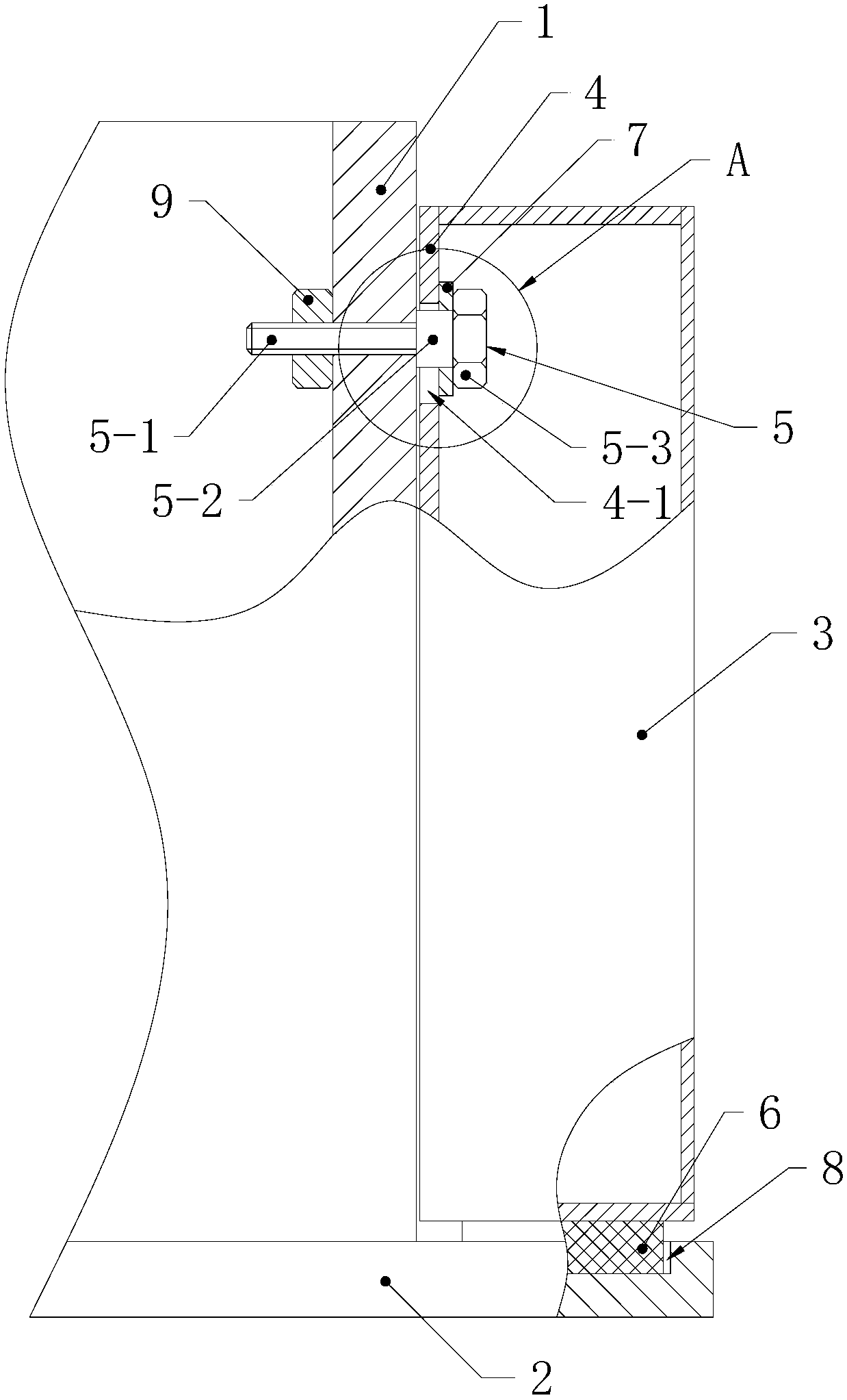
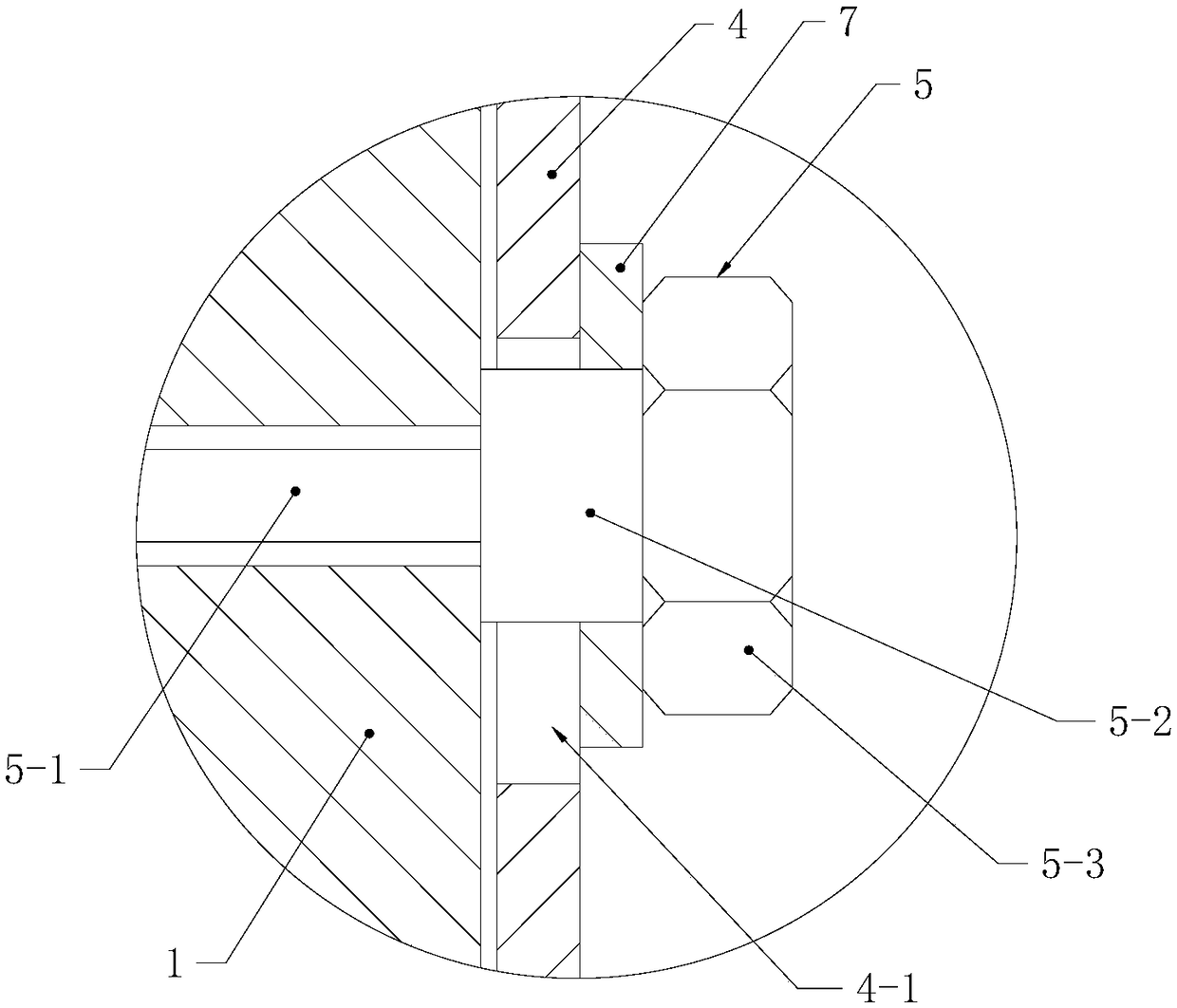
[0014] Such as figure 1 and figure 2 The high shock resistance die-cutting machine split-type electrical cabinet installation structure shown includes a die-cutting machine wall plate 1 and a bottom plate 2, the bottom of the electric cabinet box 3 rests on the bottom plate 2, and the back plate 4 of the electric cabinet box 3 is abutted on the On the wallboard 1, it is connected with the wallboard 1 by a bolt 5, wherein the bolt 5 includes a screw section 5-1, a support section 5-2, and a nut 5-3, wherein the support section 5-2 forms a cylinder Body, coaxially connected between the screw section 5-1 and the nut 5-3, the diameter of the support section 5-2 is between the diameter of the screw section 5-1 and the outer diameter of the nut 5-3, the wallboard 1 is provided with a plurality of threaded holes 1-1 matching with the screw section...


PUM


Abstract

The invention relates to a die-cutting machine split type electric cabinet box installing structure with high shock resistance. The die-cutting machine split type electric cabinet box installing structure with high shock resistance comprises a die-cutting machine wall plate and a bottom plate. The bottom of an electric cabinet box is placed on the bottom plate. A back plate of the electric cabinetbox is in butt joint with the wall plate and is connected with the wall plate through bolts. Each bolt comprises a screw rod section, a supporting section and a nut, wherein the supporting section iscoaxially connected between the screw rod section and the nut. The wall plate is provided with a plurality of threaded holes. The back plate is provided with long round holes which are in one-to-onecorrespondence with the threaded holes and extend vertically. The long round holes are matched with the supporting sections and connected with the supporting sections in a sleeving mode. The bolts penetrate through the long round holes from the inside of the electric cabinet box and are in threaded connection with the threaded holes. The axial length of each supporting section is not smaller thanthe thickness of the back plate. An elastic part is arranged between the bottom plate and the bottom surface of the electric cabinet box. As a certain gap exists between the back plate and the wall plate after the back plate and the wall plate are connected, the electric cabinet box can move relative to a machine body. Shock of the bottom plate of the machine body can be absorbed by the elastic part, so that the shock amplitude of the electric cabinet box is greatly lowered, and the service life of the electric cabinet box is prolonged.

Description

Technical field: [0001] The invention belongs to the technical field of mechanical assembly, and in particular relates to a high shock resistance die-cutting machine split-type electric cabinet box installation structure. Background technique: [0002] The die-cutting machine includes a main body and an electric cabinet. The main body includes a wall panel and a bottom plate, as well as various components arranged in the wall panel. The electric cabinet box is used as the power supply and distribution equipment of the die-cutting machine, and is usually fixedly connected to the outer wall of the wall panel. , since the working condition of the die-cutting machine is high-frequency stamping, it will inevitably bring a large vibration to the fuselage. In the state of long-term frequent vibration, the electrical equipment in the electric cabinet is easy to loosen, and the terminals are prone to fall off. Sudden electrical failures are caused, so it is necessary to regularly ove...

Claims


Application Information

Patent Timeline
IPC IPC(8): F16F15/04F16B13/10B26F1/38B26D7/00
CPCF16B13/04F16F15/04B26D7/00B26F1/38B26D2007/0012F16B13/10
Inventor 王己衣
Owner 无锡市正先自动化设备有限公司
Learn More