
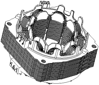
Efficient motor lead winding equipment

A technology of winding equipment and lead wire, applied in the field of high-efficiency motor lead wire winding equipment, can solve the problems of poor winding quality, deviation of winding positioning accuracy, complicated structure of winding machine, etc. Well-designed effects

Pending Publication Date: 2018-07-31
格兰德电气有限公司
View PDF0 Cites 0 Cited by
  • Summary
  • Abstract
  • Description
  • Claims
  • Application Information

AI Technical Summary

Problems solved by technology

[0003] Currently on the market, the existing patent number is 201410736455.3, and the patent name is an inner winding machine, which includes a frame, a swing nozzle, a main shaft winding mechanism, a positioning hook mechanism, a thread trimming mechanism and a rotary table; the machine The frame is provided with a rotary table, the spindle winding mechanism passes through the center of the rotary table, the upper end of the spindle winding mechanism is provided with a swing nozzle seat, and the front end of the swing nozzle seat is provided with a swing nozzle, and the swing nozzle is at least There is one, the middle part of the swing mouth seat is provided with a moving slot, the moving slot is covered on the main shaft winding mechanism, the swing mouth seat slides relative to the main shaft winding mechanism, and the front end of the swing mouth is provided with a positioning hook mechanism , the lower part of the positioning hook thread mechanism is provided with a thread trimming mechanism, etc.; by setting a plurality of swing nozzles, the multiple swing nozzles can work at the same time and improve work efficiency, but the winding machine of this structure has a complex structure, Shortcomings such as poor winding quality and deviation in winding positioning accuracy

Method used


Image

  • Efficient motor lead winding equipment
  • Efficient motor lead winding equipment
  • Efficient motor lead winding equipment

Examples


Embodiment Construction

[0022] The present invention will be further described below in conjunction with the accompanying drawings.

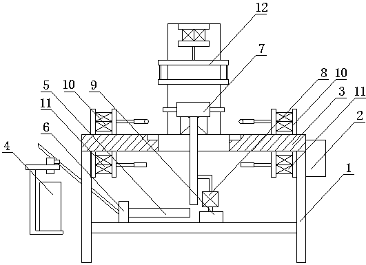
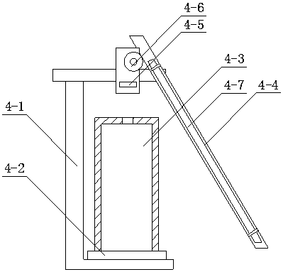
[0023] like figure 1 , figure 2 , image 3 , Figure 4 , Figure 5As shown, a high-efficiency motor lead wire winding equipment described in this embodiment includes a frame 1, a controller 2, a workbench 3, a material placement mechanism 4, a delivery pipe 5, a lead wire tension regulator 6, and a rotating and revolving assembly 7. Motor 8, lifting assembly 9, positioning hook wire mechanism 10, shearing mechanism 11 and pressing mechanism 12, workbench 3 is fixed on the frame 1, a through hole is provided on the upper surface of workbench 3, and The periphery of the through hole extends downwards with positioning slots; the lower part of the through hole facing the workbench 3 is connected with the rotating and revolving assembly 7 through the motor 8, and the motor 8 is connected with the lifting assembly 9, so that the rotating and revolving assembly 7 is in t...


PUM


Abstract

The invention relates to the technical field of motor processing, particularly efficient motor lead winding equipment, and aims to provide the efficient motor lead winding equipment capable of improving working efficiency, realizing high winding positioning accuracy and ensuring the winding quality; the efficient motor lead winding equipment comprises a rack, a controller, a working table, a material placement mechanism, a conveying pipe, a lead tension adjustor, a rotary revolution assembly, a motor, a lifting assembly, a positioning hook line mechanism, a shearing mechanism and a tighteningmechanism; the working table is fixed on the rack; a though hole is formed in the upper surface of the working table, and a positioning groove is formed in the periphery of the through hole in a downward extension manner; the downward side, aligned to the through hole of the working table, is connected with the rotary revolution assembly through the motor, and the motor is connected with the lifting assembly; and the rotary revolution assembly consists of a hollow structured feeding pipe, a rotary head, a discharging pipe and the like; and the efficient motor lead winding equipment has the characteristics of simple structure, reasonable design and convenience in use.

Description

technical field [0001] The invention relates to the technical field of motor processing, in particular to a high-efficiency motor lead wire winding device. Background technique [0002] In the whole production process of the motor, there is a process of winding the motor lead wires on the motor stator through a winding machine to form multiple windings. In the process of energy conversion of the motor, the windings play an extremely important role. When the windings are in the magnetic field When rotating, the winding will generate an induced potential, and a magnetic field will be generated when a current flows in the winding, and an electromagnetic torque will be generated if there is a current flowing in the winding in the magnetic field. [0003] Currently on the market, the existing patent number is 201410736455.3, and the patent name is an inner winding machine, which includes a frame, a swing nozzle, a main shaft winding mechanism, a positioning hook mechanism, a thre...

Claims


Application Information

Patent Timeline
IPC IPC(8): H02K15/00
CPCH02K15/0068
Inventor 许新江沈荣夏丽清刘中茂
Owner 格兰德电气有限公司
Learn More