Instrument device manipulator for a surgical robotics system
A technology of surgical instruments and manipulators, applied in the field of surgical robots
- Summary
- Abstract
- Description
- Claims
- Application Information
AI Technical Summary
Problems solved by technology
Method used
Image

Examples
Embodiment Construction
[0035] I. Surgical robotic system
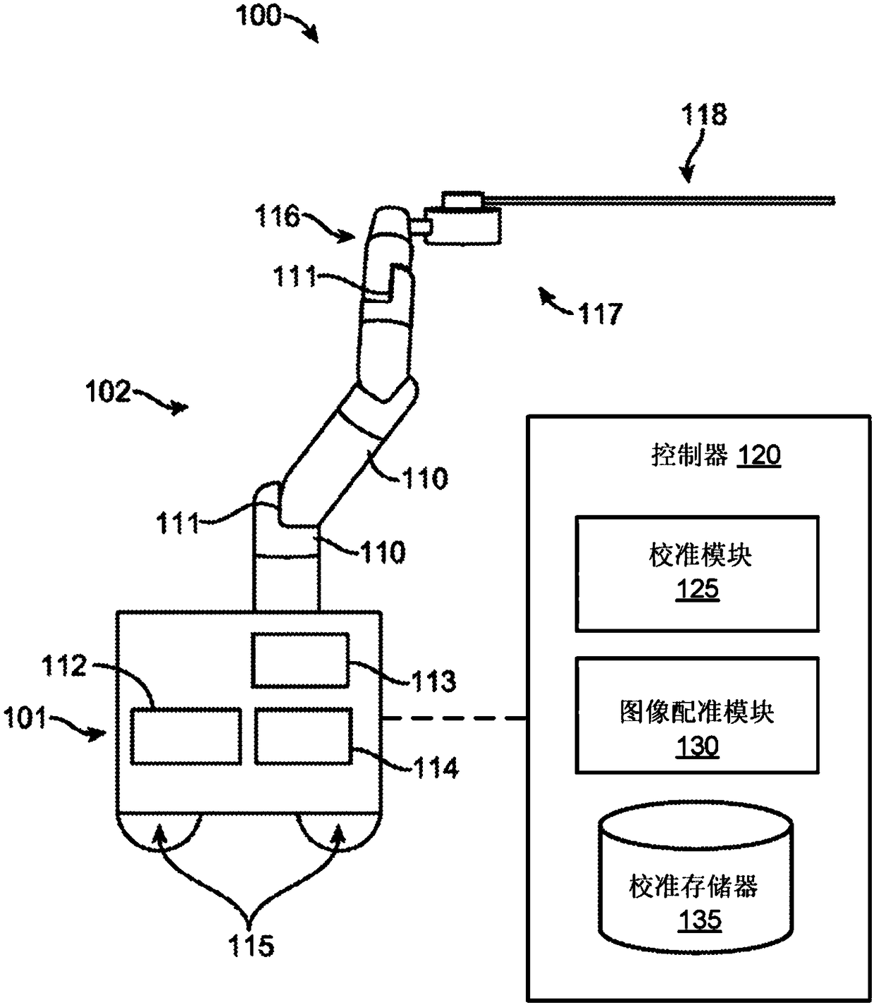
[0036] figure 1 An embodiment of a surgical robotic system 100 is shown. Surgical robotic system 100 includes a base 101 coupled to one or more robotic arms, such as robotic arm 102 . Base 101 is communicatively coupled to a command console, which is referred to herein as figure 2 is further described. Base 101 can be positioned such that robotic arm 102 can be approached to perform a surgical procedure on a patient, while a user, such as a doctor, can control surgical robotic system 100 from a comfortable command console. In some embodiments, base 101 may be coupled to a surgical table or bed for supporting a patient. Although for clarity in figure 1 Not shown in , but base 101 may include subsystems such as control electronics, pneumatics, power supplies, light sources, and the like. The robotic arm 102 includes a plurality of arm sections 110 coupled at joints 111 that provide the robotic arm 102 with multiple degrees of freedom, e...
PUM
 Abstract
Description
Claims
Application Information
PatSnap Eureka turns technology decisions into work you can execute. Powered by our Innovation Knowledge Graph, it runs expert workflows across engineering, life sciences, materials and intellectual property. Get your review-ready output in minutes.


