
Adaptive drilling with piezo-electric feed oscillator

An oscillator and feed technology, applied in the direction of manufacturing tools, metal processing machinery parts, metal processing, etc., can solve the problems of limited and expensive life of thrust bearings

Active Publication Date: 2018-07-31
APEX BRANDS
View PDF7 Cites 2 Cited by
  • Summary
  • Abstract
  • Description
  • Claims
  • Application Information

AI Technical Summary

Problems solved by technology

However, these specific thrust bearings are usually very expensive and have a limited life

Method used


Image

  • Adaptive drilling with piezo-electric feed oscillator
  • Adaptive drilling with piezo-electric feed oscillator
  • Adaptive drilling with piezo-electric feed oscillator

Examples


Embodiment Construction

[0019] Some example embodiments now will be described more fully hereinafter with reference to the accompanying drawings, in which some, but not all example embodiments are shown. Indeed, the embodiments described and described herein should not be construed as limitations on the scope, applicability or configuration of the present disclosure. Rather, these example embodiments are provided so that this disclosure will satisfy applicable legal requirements. Like reference numerals refer to like elements throughout. Furthermore, as used herein, the term "or" is to be interpreted as a logical operator that results in true whenever one or more of its operands are true. As used herein, operatively coupled should be understood to refer to a direct or indirect connection, which in either case achieves a functional interconnection of components that are operably coupled to each other.

[0020] As indicated above, some example embodiments may relate to providing high performance forc...


PUM


Abstract

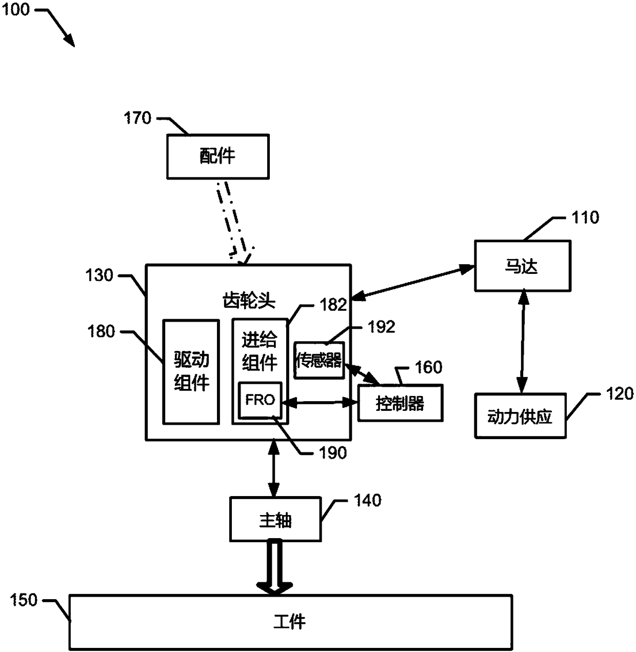
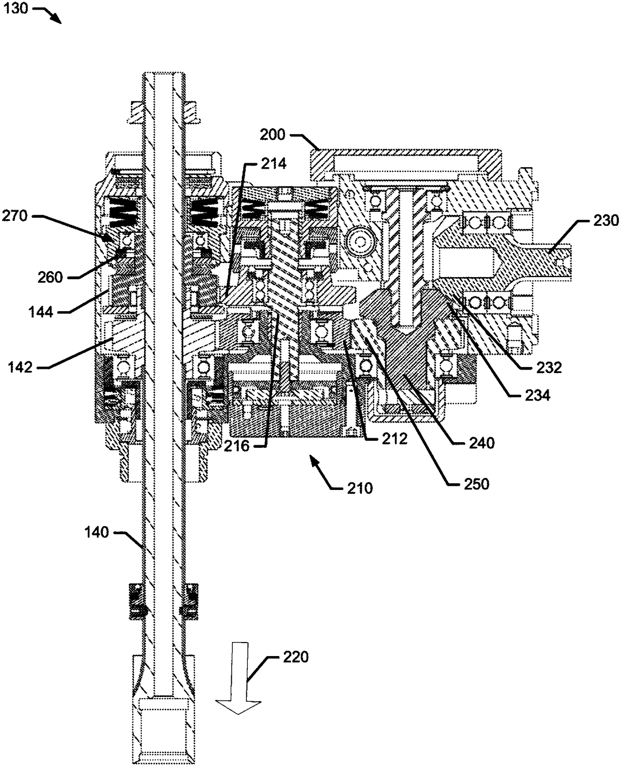
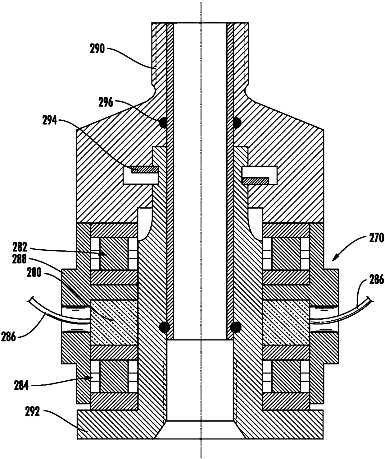
A positive feed tool may include a motor, a power supply operably coupled to the motor to power the motor, a gear head and a spindle. The gear head may be operably coupled to the motor to be operatedresponsive to powering of the motor. The gear head may include a drive assembly and a feed assembly. The spindle may be operably coupled to the gear head to enable the spindle to be selectively drivenrotationally and fed axially based on operation of the drive assembly and the feed assembly, respectively. The feed assembly may include an electronically controlled variable feed rate oscillator.

Description

[0001] Cross References to Related Applications [0002] This application claims priority to U.S. Patent Application No. 62 / 255,754, filed November 16, 2015, and U.S. Patent Application No. 14 / 990,135, filed January 7, 2016, both of which are incorporated by reference The whole is expressly incorporated herein. technical field [0003] Example embodiments relate generally to power tools, and in particular to positive feed tools employing feed rate oscillations. Background technique [0004] Power tools are commonly used in all aspects of industry and in consumer homes. Power tools are employed for a variety of applications including, for example, drilling, screwing, grinding, and the like. For some drilling operations and fastening operations, a force-feed tool may be preferred. Force-feed tools are often used to perform operations on workpieces such as steel, aluminum, titanium, and composites, and may employ a tool feed mechanism that feeds a drill bit into the workpiec...

Claims


Application Information

Patent Timeline
IPC IPC(8): B23Q5/32B23Q17/09
CPCB23Q5/326B23Q1/34B23Q17/20B23B2260/108B23B37/00B23B2270/027B23Q5/32B23Q17/0966B23Q17/0995
Inventor 亚当·唐纳德·费尔柴尔德罗尔夫·赖茨·戴斯沃特杰里米·戴恩·沃特福德
Owner APEX BRANDS
Learn More