
Method for producing fuel composition and for operating internal combustion engine

A fuel composition and internal combustion engine technology, applied in the field of producing cheap fuel composition, can solve the problems of synthetic gas consumption and expensive, and achieve the effect of improving flammability

Pending Publication Date: 2018-07-31
MOTOREN UND TURBINEN UNION MUNCHEN GMBH
View PDF7 Cites 0 Cited by
  • Summary
  • Abstract
  • Description
  • Claims
  • Application Information

AI Technical Summary

Problems solved by technology

Generating synthesis gas is a costly and expensive process

Method used


Image

  • Method for producing fuel composition and for operating internal combustion engine

Examples


Embodiment Construction

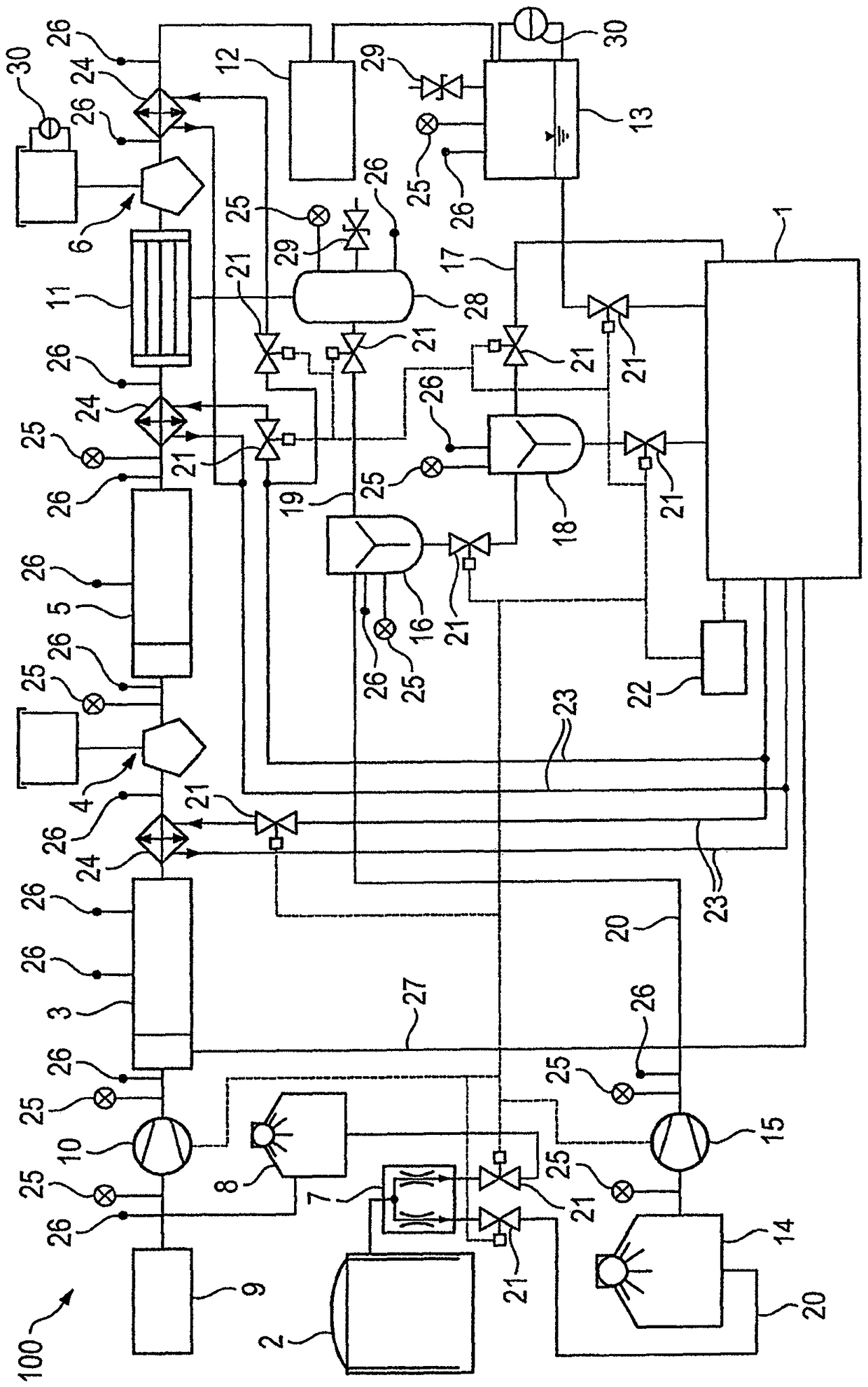
[0024] figure 1Relevant components of a system 100 are shown, which are suitable for operating an internal combustion engine according to an advantageous development of the method. The device includes internal combustion engine 1, special gas source 2, reformer 3, CO 2 Separator 4 , DME generating device 5 and methanol separator 6 . First, a special gas containing a combustible substance is supplied from the special gas source 2 . Suitable special gases include waste and associated gases from the chemical industry and raw material production (e.g. from refining), wood gas, conversion gas, pyrolysis gas, biogas and pit gas, coke oven gas, landfill gas, biogas , sewage gas, natural gas, flare gas, shale gas, city gas, propane, butane, associated gases formed in the production of steel and iron (for example: iron furnace gas, blast furnace gas, etc.) composed mixture. The special gas is conducted through a flow splitter 7, which separates the special gas into a first part and...


PUM


Abstract

The invention relates to a method for producing a fuel composition. Said method comprises the following steps: special gas containing combustible substances is provided, a first part of the special gas is reformed by producing synthesis gas, dimethyl ether is produced from the synthesis gas by producing a reaction mixture containing a dimethyl ether, methanol is separated from the reaction mixtureand a methanol-reduced dimethyl ether mixture is produced, a second part of the special gas is brought together with the methanol reduced dimethyl ether mixture in order to obtain the fuel composition.

Description

technical field [0001] The present invention relates to a method for producing inexpensive fuel components. Furthermore, the invention relates to a method for operating an internal combustion engine. Furthermore, the use of methanol-reduced dimethyl ether is also described according to the invention. Background technique [0002] The efficiency of an internal combustion engine essentially depends on the energy content and composition of the fuel mixture used. Thus, for example, synthesis gas produced by reformation is used, which contains a high proportion of flammable hydrogen. Generating synthesis gas is a laborious and expensive process. Synthesis gas can be produced from special gases through purification and subsequent transformation. Special gases that also contain lean gases are usually exhaust gases, which accumulate, for example, during gas transport or in biological or chemical processes and are usually flared or are discharged into the environment without addi...

Claims


Application Information

Patent Timeline
Patent Type & Authority Applications(China)
IPC IPC(8): C10L3/00F02D19/06
CPCC10L3/003F02D19/0647F02D19/085C10L2290/04C10L2270/02C10L2290/24C10L2290/02C10L2290/54C10K3/06C10L1/1852C10L3/06F02D19/0671Y02T10/30Y02E50/30C01B3/34C01B2203/0205C01B2203/0475C01B2203/06C07C41/01F02B7/06F02D19/082
Inventor M.黑勒P.克拉斯
Owner MOTOREN UND TURBINEN UNION MUNCHEN GMBH
Features
  • Generate Ideas
  • Intellectual Property
  • Life Sciences
  • Materials
  • Tech Scout
  • Unparalleled Data Quality
  • Higher Quality Content
  • 60% Fewer Hallucinations
Learn More