Controlled stopping method for textile machine and textile machine stopped by this process

A technology for textile machines and control equipment, applied in the direction of controlling multiple DC motors, controlling multiple AC motors, motor control, etc., can solve the problems of reduction, unstable control of intermediate circuit voltage, etc.

Active Publication Date: 2018-07-31
N V MICHEL VAN DE WIELE
View PDF5 Cites 2 Cited by
  • Summary
  • Abstract
  • Description
  • Claims
  • Application Information

AI Technical Summary

Problems solved by technology

[0013] A further disadvantage of this approach to energy recovery is that due to the continuously decreasing speed, the energy gain varies continuously with the same change as the speed
At low machine speeds this can lead to an unstable control of the voltage on the intermediate circuit, and this must be the case if the load connected to the intermediate circuit is of a highly dynamic type

Method used


Image

  • Controlled stopping method for textile machine and textile machine stopped by this process
  • Controlled stopping method for textile machine and textile machine stopped by this process
  • Controlled stopping method for textile machine and textile machine stopped by this process

Examples


Embodiment Construction

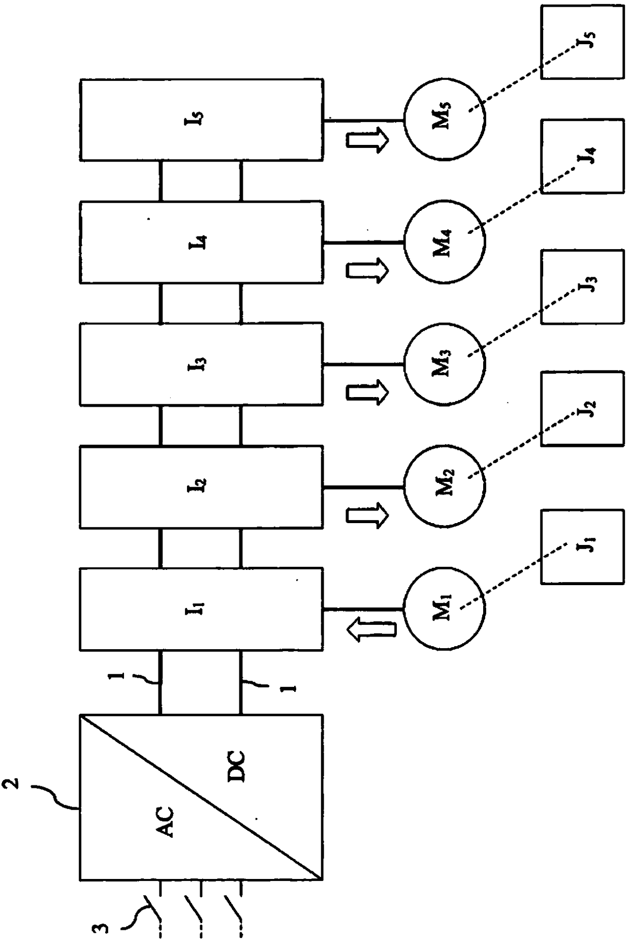
[0062] figure 1 The textile machine according to the invention in the schematically shown embodiment has a motor (M 1 , M 2 , M 3 , M 4 , M 5 ) driven by 5 axes. Each axis has its own inertia (J 1 、J 2 、J 3 、J 4 、J 5 ). through a separate motor controller (I 1 ), (I 2 ), (I 3 ), (I 4 ), (I 5 ) controls the motor and said motor is connected to a common intermediate voltage circuit (1) or "common DC bus". In normal operating conditions, they are supplied with power from the mains source via the AC / DC converter (2) and the switching device (3).

[0063] Via the motor on the left hand side (M 1 ) is driven by the axis with the highest energy content or the energy-dominant axis. On a knitting machine, this is the spindle. The word "axis" is used not only to mean the axis itself, but also all parts that are set in motion by this axis. "Energy content" means kinetic energy, said kinetic energy of motion with rotation being the inertia of the shaft according to the...


PUM


Abstract

The invention relates to a method and a device for bringing a textile machine to a controlled standstill in the event of a failure of the power supply, and to a correspondingly equipped textile machine, the textile machine having at least two axes that are driven in synchronization by respective electric motors (MI-M5) connected to a common intermediate voltage circuit (1), and in which at least one electric motor acting as power generator can supply electric power to at least one other electric motor via the common DC bus (1), and in which the voltage (V) on the common DC bus is controlled byvarying at least two variables in such a way that the voltage follows a previously defined curve while the textile machine is being brought to a standstill.

Description

technical field [0001] The invention relates to a method and a control device for bringing a textile machine into a controlled quiescent state in the absence of a power supply, said textile machines having been provided to be driven synchronously by respective electric motors connected to a common intermediate voltage circuit and wherein at least one electric motor acting as a generator is capable of supplying electrical power to at least one other electric motor via an intermediate voltage circuit. [0002] This invention also relates to a textile machine having the characteristics indicated in the preceding paragraphs, said textile machine being equipped with a control device for bringing it into a controlled standstill. Background technique [0003] The term "shaft" as used herein means the motor shaft and the moving motor parts and all parts driven therethrough, such as transmissions and the like. The term "textile machine" is used in the sense of any facility for produ...

Claims


Application Information

Patent Timeline
Patent Type & Authority Applications(China)
IPC IPC(8): H02P5/74H02P29/028H02P5/68H02P29/024
CPCH02P29/025H02P29/026H02P5/68H02P29/032H02P5/74
Inventor G.德比夫W.拉苏伊特
Owner N V MICHEL VAN DE WIELE
Why Eureka
Try Eureka