Passive turbine emulsifier

A passive, emulsifying machine technology, applied in mixers, chemical instruments and methods, chemical/physical processes, etc., can solve problems such as power consumption, impact on service life, increase production costs, etc., to reduce process flow and improve work efficiency Effect

Pending Publication Date: 2018-08-03
HUNAN KENON SCI & TECH
View PDF11 Cites 1 Cited by
  • Summary
  • Abstract
  • Description
  • Claims
  • Application Information

AI Technical Summary

Problems solved by technology

[0002] In the existing emulsifiers, most of them use motors to provide kinetic energy. The motor drives the rotating shaft to rotate, which not only consumes electric energy, but also requires additional protection sensors to order the subsequent process to stop when the emulsifier is stopped.
It not only increases the production cost, but also generates heat accumulation due to idling of the emulsifier, which affects th

Method used


Image

  • Passive turbine emulsifier
  • Passive turbine emulsifier
  • Passive turbine emulsifier

Examples


Embodiment Construction

[0027] The present invention will be further described below in conjunction with specific embodiments. Among them, the drawings are only used for exemplary description, and they are only schematic diagrams rather than physical drawings, and cannot be understood as a limitation of the patent; in order to better illustrate the embodiments of the present invention, some parts of the drawings may be omitted, Enlargement or reduction does not represent the size of the actual product; for those skilled in the art, it is understandable that some well-known structures in the drawings and their descriptions may be omitted.

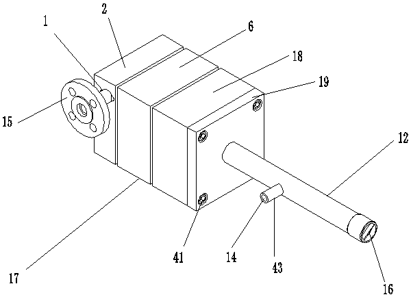
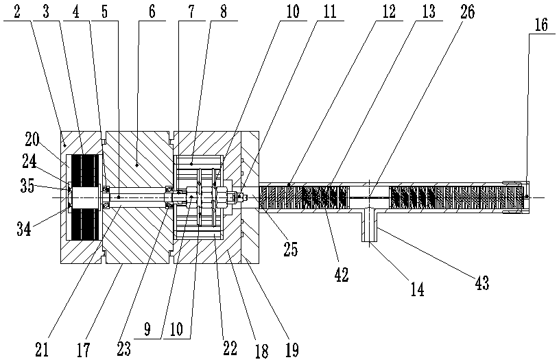
[0028] Such as figure 1 , figure 2 As shown, a passive turbo emulsifier includes a housing 17, a power cavity, a bearing housing cavity 6, an emulsification cavity 18, an end cover 19, a first cavity 20, a second cavity 21, and a third cavity 22. The first feed port 1, the left bearing 4, the right bearing 23, the emulsification shaft 5, the disc group 3, the fixed p...


PUM


Abstract

The invention relates to a passive turbine emulsifier. The passive turbine emulsifier comprises a shell, an emulsifying shaft, a disk group, shearing blades and a stator grid, wherein a first cavity,a second cavity and a third cavity are arranged in the shell; the emulsifying shaft is fixedly arranged in the second cavity through a left bearing and a right bearing; the disk group and a fixed sheet are arranged at the left end of the emulsifying shaft; the shearing blades and the stator grid are arranged at the right end of the emulsifying shaft; the center of an end cover is provided with a first discharge hole; the right side of the first discharge hole is connected with a discharge pipe. By adopting the passive turbine emulsifier, additional power driving is not needed, thereby loweringthe production cost. No additional protection sensing device is needed, and heat generated during mechanical rotation can be brought away.

Description

Technical field [0001] The invention relates to the field of emulsification machinery, in particular to a passive turbine emulsifier. Background technique [0002] Most of the existing emulsifiers use motors to provide kinetic energy. The motors drive the rotating shaft to rotate, which not only requires power consumption, but also requires additional protection sensors to order the subsequent processes to stop when the emulsifier is stopped. This not only increases the production cost, but also generates heat accumulation due to the idling of the emulsifier, which affects the service life. At the same time, in the prior art, the rotating shaft generates heat due to rotation, causing the rotating shaft to heat up, and to reduce the friction between the rotating shaft and the bearing, the rotating shaft must be coated with lubricating oil at regular intervals, which not only requires disassembly of parts but also It may also contaminate the product. Summary of the invention [00...

Claims


Application Information

Patent Timeline
IPC IPC(8): B01F13/10B01F7/00B01F5/06B01F3/08
CPCB01F23/43B01F25/42B01F27/27B01F27/55B01F33/82
Inventor 张璞杨佳王少波朱晓华汪惊奇何春辉吴细兵
Owner HUNAN KENON SCI & TECH
Why Eureka
Try Eureka