
Drying cooling device and drying cooling system for energetic materials

A drying, cooling and drying technology, which is applied in the direction of drying solid materials, heating devices, drying, etc., can solve the problems of toxicity of small molecules, difficulty in deriving excess heat, easy combustion or explosion, etc., and achieve the effect of strengthening the drying and cooling process

Inactive Publication Date: 2014-04-23
XIAN MODERN CHEM RES INST
View PDF2 Cites 6 Cited by
  • Summary
  • Abstract
  • Description
  • Claims
  • Application Information

AI Technical Summary

Problems solved by technology

[0003] (1) The gap between the tray and the heating steam pipe in the oven is generally small, causing the air temperature near the tray to be easily out of control, resulting in overheating. For example, if the oven temperature is set at 90°C, the local temperature of the tray may reach 140-150°C;
[0004] (2) The oven is a drying equipment in a closed space. Once the temperature is not controlled, it is difficult to export the excess heat, but it will accumulate more and more, which will eventually lead to safety accidents;
[0005] (3) At present, the drying operation of the oven is discontinuous and requires a lot of manual operations, such as putting the tray containing the dried material into the oven, taking the dried material out of the oven, and controlling the drying process, all of which require human participation , thus leaving a great security risk;
[0006] (4) The material at the bottom of the tray is first heated. Due to the thick material layer, it is difficult for the bottom material to reach the predetermined temperature to export heat in time, resulting in heat accumulation and a sudden rise in temperature. If the material to be dried is an energetic material, once it reaches its decomposition temperature , energetic materials will decompose into small molecules such as nitrogen oxides, these small molecules are toxic, and are very easy to burn or explode after being heated at high temperature, thus causing safety accidents
[0007] Therefore, for the drying treatment of energetic material particles such as TNAZ, the use of an oven for drying operation has natural safety drawbacks, which will greatly increase the possibility of danger, leading to safety accidents and product quality issues.

Method used


Image

  • Drying cooling device and drying cooling system for energetic materials
  • Drying cooling device and drying cooling system for energetic materials

Examples


Embodiment

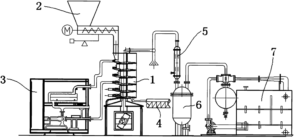
[0040] This embodiment is a specific dry cooling system. refer to figure 2 , the whole system is composed of water heater 3, twin-screw automatic feeder 2, drying and cooling device 1 of the present invention, automatic belt discharge conveyor 4, tube condenser 5, buffer tank 6, and water jet vacuum pump 7.

[0041] Start the water pump before drying, set the heating temperature of the circulating deionized water, start the power supply of the control cabinet, turn on the water heater, and the circulating pure water enters the spiral coil cavity through the pipeline. There are six layers of spiral coils, of which the upper four layers are The drying plate, the lower two layers are cooling plates, the hot water inlet pipe and the outlet pipe are respectively connected to the first and fourth stage coils, the cooling water is tap water at normal temperature, and the inlet pipe and outlet pipe are respectively connected to the fifth and fourth stage coils. The sixth-stage spira...


PUM


Abstract

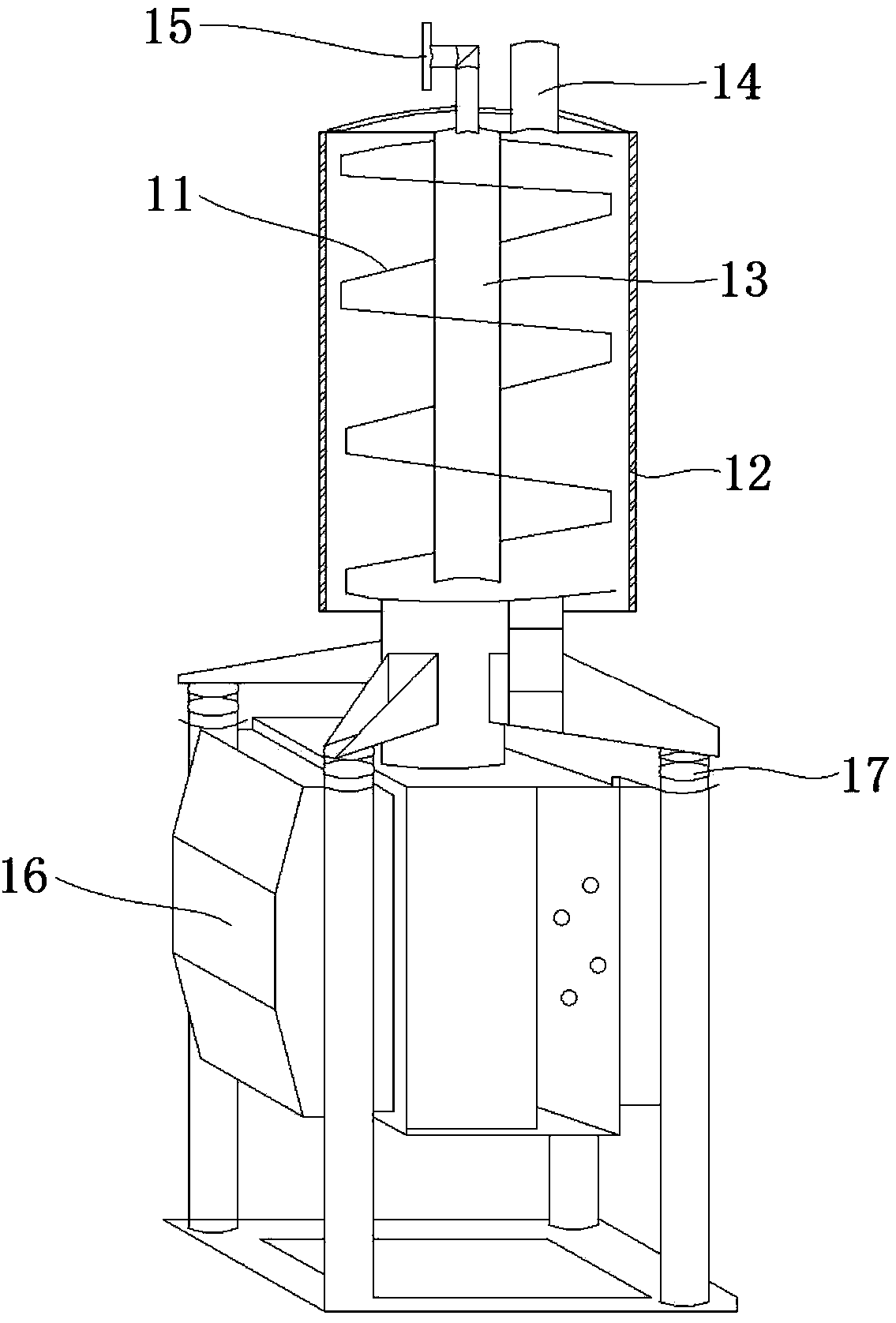
The invention relates to a drying cooling device and a drying cooling system for energetic materials. The device comprises a spiral disc which is in a cavity structure. To-be-dried materials are held on the spiral disc, feeding is performed along the rotation extending direction of the spiral disc, and the to-be-dried materials are dried by thermal media in the disc cavity and then cooled by cooling media in the disc cavity during feeding. The drying cooling system comprises a feeding machine, the drying cooling device, a discharging delivery machine, a water heater, a condenser and a vacuum pump. According to the drying cooling device and the drying cooling system, the materials in the drying cooling device are fed through the outer surface of the spiral disc, hot water and cooling water are fed through the spiral disc cavity, so that material drying and cooling processes can be observed. When the energetic materials are dried by the system, the whole process is completed in a control room away from a workshop, so that workers and machines are completely separated, and potential safety hazards are eliminated.

Description

technical field [0001] The invention relates to material drying technology, in particular to a drying cooling device and a vibration drying cooling system for energetic materials. Background technique [0002] A traditional means of drying energetic material particles is an oven. Multi-layer trays are arranged in the oven space to contain energetic material particles to be dried, and the temperature in the oven is raised by the heat transfer of high-pressure steam. In recent years, safety accidents in the process of drying energetic material particles in an oven are not uncommon. Although the reasons are complicated, the intrinsic safety of the process cannot be guaranteed from the analysis of the principle of drying energetic material particles in an oven. Its disadvantages are mainly reflected in the following aspects: [0003] (1) The gap between the tray and the heating steam pipe in the oven is generally small, causing the air temperature near the tray to be easily ou...

Claims


Application Information

Patent Timeline
Patent Type & Authority Applications(China)
IPC IPC(8): F26B17/12F26B23/10F26B25/00
Inventor 张亮杨毅陈松秦能马宁邹高兴李萌康超
Owner XIAN MODERN CHEM RES INST
Learn More