
Numerically controlled lathe tool changing frame

A technology of CNC lathes and tool rests, which is applied in the direction of manufacturing tools, metal processing machinery parts, positioning devices, etc., can solve the problems of shortened life, easy for operators to forget to add, can not achieve lubrication effect, etc., and achieve the effect of prolonging service life.

Inactive Publication Date: 2022-05-24
江苏恩格尔智能科技有限公司
View PDF0 Cites 2 Cited by
  • Summary
  • Abstract
  • Description
  • Claims
  • Application Information

AI Technical Summary

Problems solved by technology

It is mainly used for the cutting of shaft parts or disc parts. The tool holder of CNC lathe can be equipped with multiple turning tools, and the turning tool with different functions can be replaced by rotating the tool holder. The tool holder has high precision requirements. The frame will regularly inject lubricating oil inwards. The ordinary oiling device is directly injected into the internal parts. The lubricating oil lubricating time is short and the operator tends to forget to add lubricating oil after long-term use. The lubricating effect is reduced and the service life is shortened. Finally, the internal lubricating oil will remain inside the tool holder for a long time, and the lubrication effect will not be achieved, which will cause damage to the machine in the long run

Method used


Image

  • Numerically controlled lathe tool changing frame
  • Numerically controlled lathe tool changing frame
  • Numerically controlled lathe tool changing frame

Examples


Embodiment

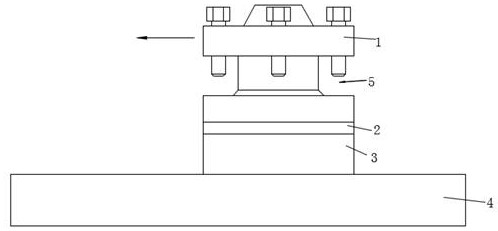
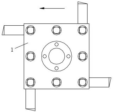
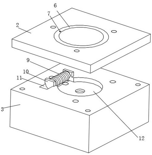
[0026] like Figure 1-Figure 7 As shown, in this embodiment, a tool changer for a CNC lathe is provided, which includes a slide rail 4 and a tool change device that can slide along the length direction of the slide rail 4. Rotating workpiece processing also adopts this type of processing method in the present invention. The tool changer slides along the slide rail 4, which is a commonly used method in existing machining, so this method will not be elaborated in detail. Connecting plate 2 and fixed seat 3, the middle part of described tool holder 1 is provided with arranging tool groove 5, and the top of described arranging tool groove 5 is penetrated with fixing bolt, and arranging tool groove 5 is the groove that is arranged on tool holder 1 middle part, combines figure 2 As shown, four handles can be installed on the four corners of the tool holder 1 in the circumferential direction. The connecting plate 2 and the fixing seat 3 are fixedly connected, and the connecting plat...


PUM


Abstract

The invention discloses a tool changing frame of a numerically controlled lathe, which belongs to the technical field of machining and comprises a slide rail and a tool changing device capable of sliding along the length direction of the slide rail, and a driving mechanism for driving an output shaft to rotate is mounted in a driving groove; a plurality of balls used for supporting the tool frame to rotate are arranged at the joint of the tool frame and the connecting plate, a through hole is formed in the position, located below the balls, in the connecting plate and communicates with the driving groove, and an oil storage cavity is formed in the tool frame and extends to the surfaces of the balls. And in the rotating process of the ball body, lubricating oil in the oil storage cavity can be attached to the surface of the ball body, flows into the driving groove from the through hole along with the ball body and drips at the connecting position of the worm and the worm disc, the problems that automatic oil feeding cannot be achieved and waste oil always remains in the device can be solved, and the service life of the device is prolonged.

Description

technical field [0001] The invention relates to a tool changer for a numerically controlled lathe, which belongs to the field of machining technology. Background technique [0002] CNC lathe is one of the most widely used CNC machine tools. It is mainly used for the cutting of shaft parts or disc parts. The tool holder of CNC lathe can be equipped with multiple turning tools, and the turning tool with different functions can be replaced by rotating the tool holder. The tool holder has high precision requirements. The frame will regularly inject lubricating oil inwards. The ordinary oiling device is directly injected into the internal parts. The lubricating oil lubricating time is short and the operator tends to forget to add lubricating oil after long-term use. The lubricating effect is reduced and the service life is shortened. Finally, the internal lubricating oil will remain inside the tool holder for a long time, and the lubrication effect will not be achieved, which wi...

Claims


Application Information

Patent Timeline
Patent Type & Authority Applications(China)
IPC IPC(8): B23Q3/155B23Q11/12
CPCB23Q3/15526B23Q11/12Y02P70/10
Inventor 董莉
Owner 江苏恩格尔智能科技有限公司
Learn More