
Centralized driving type multi-pass nonferrous metal rolling mill

A non-ferrous metal, centralized drive technology, applied in the direction of metal rolling, metal rolling, metal processing equipment, etc., can solve the problem of gearbox lubricating oil purification and cooling, reduced service life of lubricating oil, reduced service life of gears, etc. problem, to achieve good lubrication effect, reduce the number of replacements, and reduce wear and tear

Inactive Publication Date: 2021-03-09
ZHEJIANG CHUANBOZHE METAL DECOUATION MATERIAL CO LTD
View PDF6 Cites 3 Cited by
  • Summary
  • Abstract
  • Description
  • Claims
  • Application Information

AI Technical Summary

Problems solved by technology

[0005] Aiming at the deficiencies of the prior art, the present invention provides a centralized-driven multi-pass non-ferrous metal rolling mill, which solves the problem that the existing centralized-driven multi-pass non-ferrous metal rolling mill does not have the problem of lubricating oil in the gear box. Purification and cooling functions, and the lubricating oil in the gearbox can not be evenly sprayed on the multiple gears in the gearbox to lubricate them, which will easily lead to dry grinding between the gears and increase the wear of the gears. As a result, the service life of multiple gears in the gearbox is reduced, and the lubricating oil needs to be replaced frequently, which leads to a reduction in the service life of the lubricating oil and increases the economic cost

Method used


Image

  • Centralized driving type multi-pass nonferrous metal rolling mill
  • Centralized driving type multi-pass nonferrous metal rolling mill
  • Centralized driving type multi-pass nonferrous metal rolling mill

Examples


Embodiment Construction

[0027]The following will clearly and completely describe the technical solutions in the embodiments of the present invention with reference to the accompanying drawings in the embodiments of the present invention. Obviously, the described embodiments are only some, not all, embodiments of the present invention. Based on the embodiments of the present invention, all other embodiments obtained by persons of ordinary skill in the art without making creative efforts belong to the protection scope of the present invention.

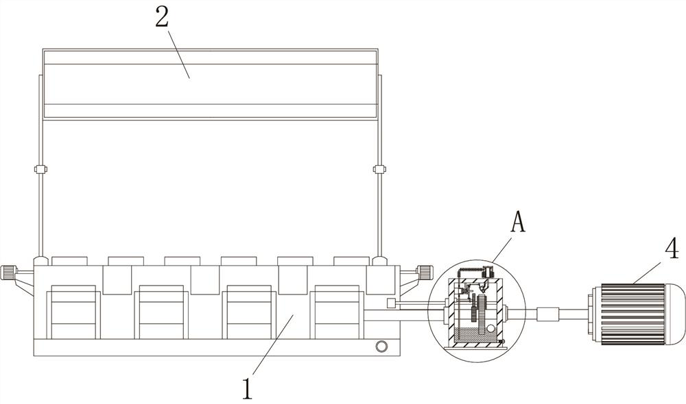
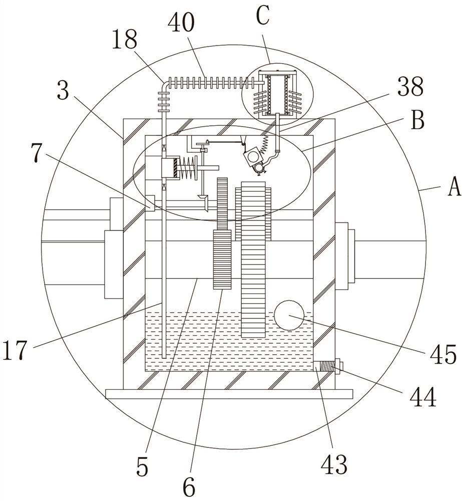
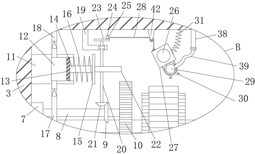
[0028] Such as Figure 1-5 As shown, the present invention provides a technical solution: a centralized-driven multi-pass non-ferrous metal rolling mill, including a rolling mill main body 1, a rolling mill safety cover 2, a gear box 3 and a motor 4, and a main shaft 5 is installed in the gear box 3 for rotation , the fixed sleeve on the main rotating shaft 5 is provided with a first transmission spur gear 6, a bearing seat 7 is fixedly installed on the inner w...


PUM


Abstract

The invention discloses a centralized driving type multi-pass nonferrous metal rolling mill. The centralized driving type multi-pass nonferrous metal rolling mill comprises a rolling mill body, a rolling mill safety hood, a gear box and a motor, a main rotating shaft is rotationally installed in the gear box, a first transmission straight gear is fixedly arranged on the main rotating shaft in a sleeving mode, a bearing seat is fixedly installed on the inner wall of one side of the gear box, a transverse shaft is rotationally installed on one side of the bearing seat, a first bevel gear is arranged on the transverse shaft in a sleeving mode, and one end, away from the bearing seat, of the transverse shaft is fixedly sleeved with a second transmission straight gear. The centralized driving type multi-pass nonferrous metal rolling mill is reasonable in design and good in practicability, effective purifying and cooling can be carried out on lubricating oil in the gear box, the lubricatingoil is evenly sprayed to the plurality of gears in the gear box by utilizing reciprocating left-right swing of a plurality of spray heads, and therefore the lubricating effect on the plurality of gears is improved, abrasion between the gears is reduced, the service life of the plurality of gears in the gear box can be prolonged, the replacement frequency of the lubricating oil can be reduced, theservice life of the lubricating oil can be prolonged, and the economic cost is reduced.

Description

technical field [0001] The invention relates to the technical field of rolling mills, in particular to a centralized-driven multi-pass non-ferrous metal rolling mill. Background technique [0002] The rolling mill is the equipment to realize the metal rolling process. It generally refers to the equipment that completes the whole process of rolling material production. According to the number of rolls, the rolling mill can be divided into two rolls, four rolls, six rolls, eight rolls, twelve rolls, eighteen rolls, etc.; According to the arrangement of the rollers, it can be divided into "L", "T", "F", "Z" and "S". Roll temperature adjustment device, transmission device, lubrication system, control system and roll removal device, etc. In addition to the main components and devices of ordinary rolling mills, precision calenders have added devices to ensure rolling accuracy. Non-ferrous metals are also called non-ferrous metals. It is a general term for all metals other than ir...

Claims


Application Information

Patent Timeline
Patent Type & Authority Applications(China)
IPC IPC(8): B21B27/10B01D29/11
CPCB21B27/10B01D29/11
Inventor 田超叶寿喜许路坤谢舍东童秋明石付宗金伟建舒智广李祥张杰新陶宇俊
Owner ZHEJIANG CHUANBOZHE METAL DECOUATION MATERIAL CO LTD
Learn More