

Clamping-ring-type front driving axle housing assembly
A front drive axle and front drive technology, applied in axles, wheels, transportation and packaging, etc., can solve the problems of high cost, difficult processing, and high strength requirements for snap ring grooves, and achieve low production cost, small processing difficulty, and applicable Wide range of performance effects
- Summary
- Abstract
- Description
- Claims
- Application Information
AI Technical Summary
Problems solved by technology
Method used
Image

Examples
Embodiment 1
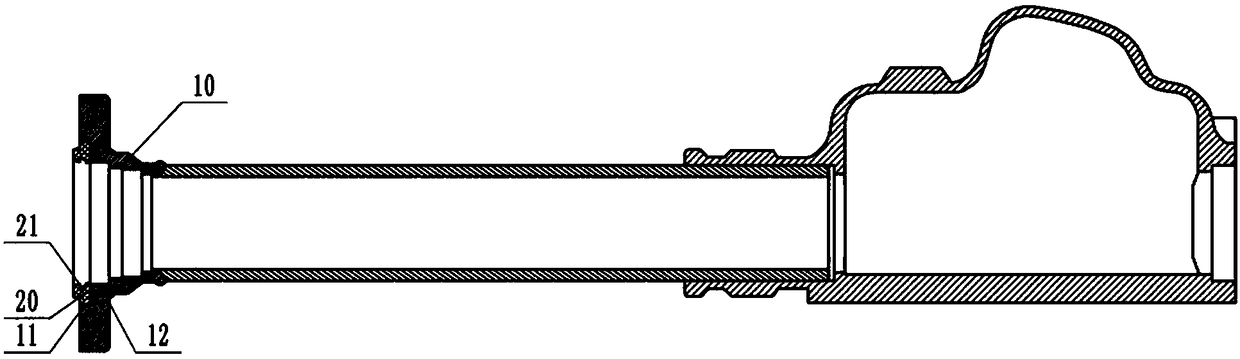
[0020] Such as figure 1 As shown, the snap ring type front drive axle housing assembly includes the front drive axle housing 10 and the snap ring 20, the snap ring 20 is processed with a snap ring groove 21; the front drive axle housing 10 is provided with an inner hole 12, and the front drive axle One end of the shell 10 is provided with a shaft hole 11 coaxial with the inner hole 12 , the inner diameter of the shaft hole 11 is smaller than the outer diameter of the snap ring 20 , and the outer end of the snap ring 20 is pressed into the shaft hole 11 by a press.
[0021] According to the analysis of the function of the snap ring groove 21 and the stress situation, the structure of the split type of the snap ring groove 21 and the front drive axle housing 10 is adopted, and the structure of the snap ring 20 is added, and the snap ring groove 21 is processed on the snap ring 20, and then the The snap ring 20 is press-fitted into the front drive axle housing 10 assembly, and th...
Embodiment 2
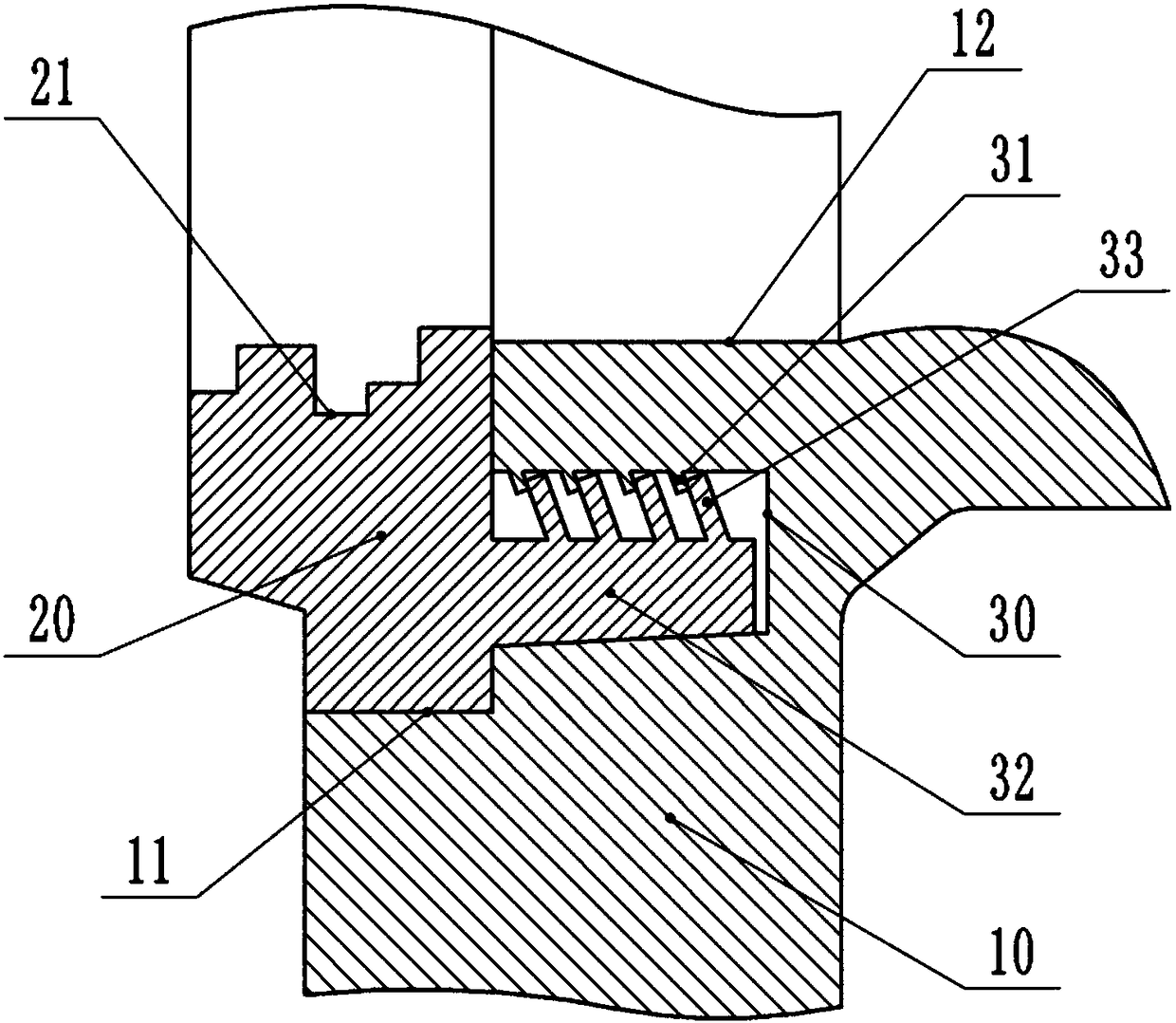
[0023] The difference between this embodiment and embodiment 1 is that, as figure 2 As shown, the inner diameter of the inner hole 12 is smaller than the inner diameter of the shaft hole 11, and a plurality of grooves 30 arranged axially along the inner hole 12 are provided on the step surface at the joint between the inner hole 12 and the shaft hole 11. There are four grooves 30 , which are evenly spaced on the same circumference; one end of the snap ring 20 close to the front drive axle case 10 is provided with four engaging parts engaging with the grooves 30 . After the snap ring 20 is pressed into the shaft hole 11 , the engaging portion will be pressed into the groove 30 , so that the connection between the snap ring 20 and the front drive axle case 10 is more firm.
[0024] The side of the groove 30 close to the center of the shaft hole 11 has a plurality of protrusions 31, and the protrusion 31 forms an angle with the side of the inner wall of the groove 30 close to th...
Embodiment 3
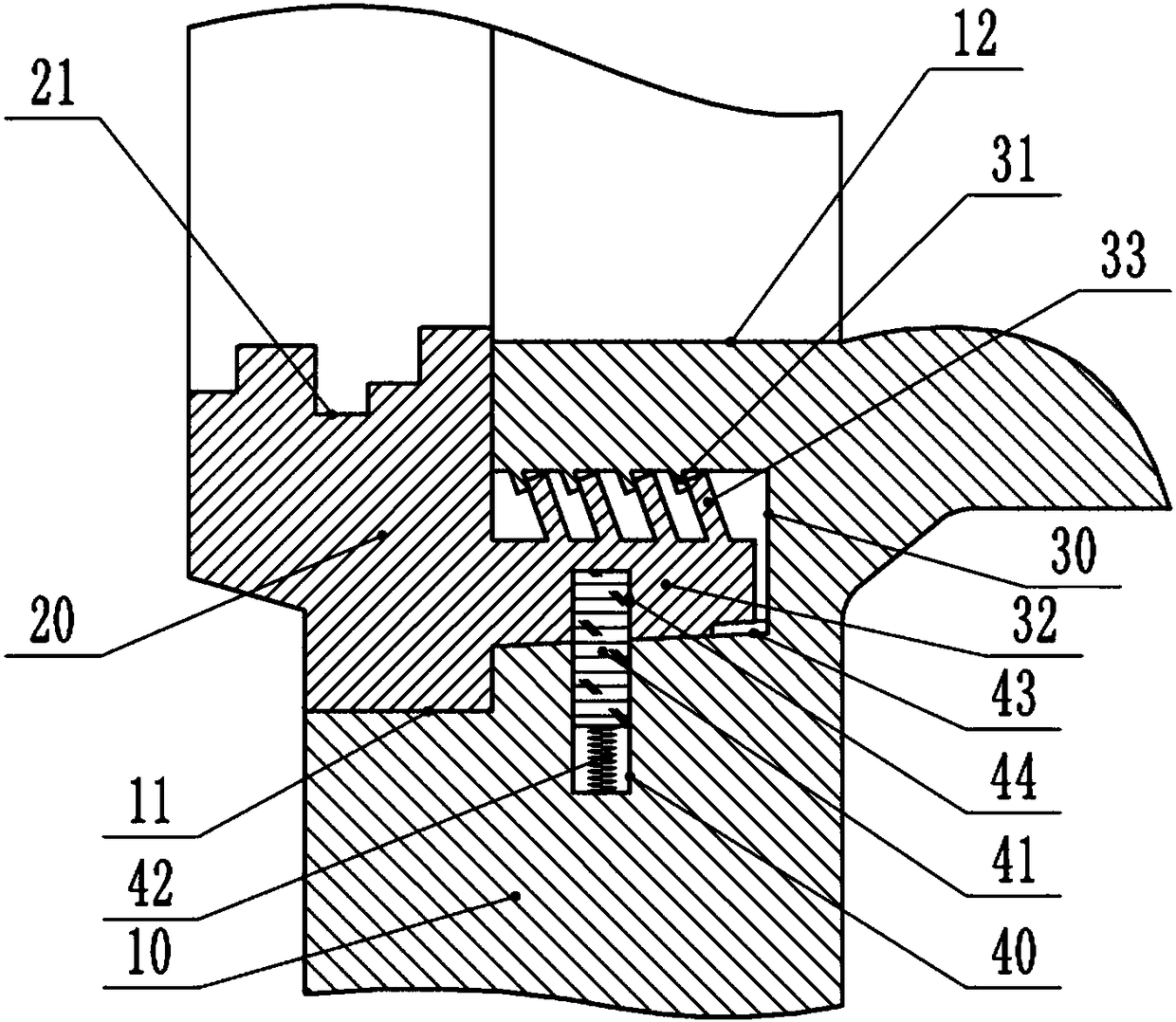
[0026] The difference between this embodiment and embodiment 2 is that, as image 3 As shown, the front drive axle case 10 is located on the first slope and is provided with a blind hole 40 perpendicular to the inner hole 12. An insert block 41 is slidably connected to the blind hole 40, and an elastic joint is connected between the insert block 41 and the bottom of the blind hole 40. The piece 42 is slidably connected with a blocking piece blocking the insert block 41 on the first slope, and the block 33 is provided with a card hole 44 for inserting the insert block 41 . When the engaging part extends into the groove 30, the blocking piece can be pushed, so that the rib is removed without blocking the plug 41, and when the blind hole 40 is aligned with the clip hole 44, the plug 41 will be inserted into the clip hole 44 , so as to further increase the connection strength between the snap ring 20 and the front drive axle case 10 .
PUM
 Abstract
Description
Claims
Application Information