

Hydrological cableway oiling machine
A technology of hydrological cableway and oil tanker, which is applied to mechanical equipment, engine components, lubricating oil containers, etc., can solve the problems of heavy, dangerous, long time, etc., to save the amount of butter, avoid waste, and reduce the consumption of labor costs. Effect
- Summary
- Abstract
- Description
- Claims
- Application Information
AI Technical Summary
Problems solved by technology
Method used
Image

Examples
Embodiment 1
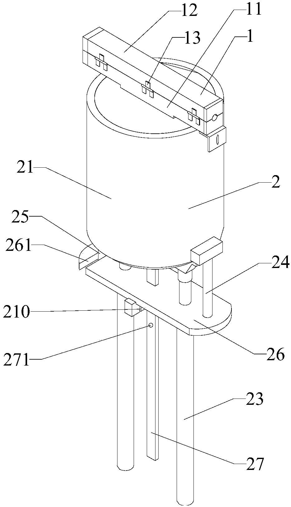
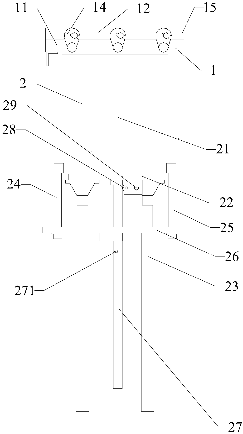
[0039]A hydrological cableway refueling machine, comprising an oiler 1 and an oil container 2; the oil container 2 includes a container 21, a pressing plate 22 and an air pressure rod 23; the container 21 includes a cylindrical inner cavity, and the pressing plate 22 The piston rod connected to the air pressure rod 23, the edge of the pressure plate 22 is sealed and slidably connected with the lower end of the inner cavity of the container 21; the upper end of the inner cavity is provided with a discharge port, and the shape of the oiler 1 is a cuboid , the oiler 1 is provided with a strip-shaped cavity, the inner cavity of the container 21 communicates with the cavity of the oiler 1 through the discharge port; the cavity of the oiler 1 is sleeved on the cableway, so One end of the cavity is sealed and connected with the cable track, and the other end is gap-fitted with the cable track; the oil receiver 2 includes a main body 11 and a cover body 12, the main body 11 is connecte...
Embodiment 2
[0042] A hydrological cableway refueling machine described in Embodiment 1, further comprising the following features: the oiler 1 and the oiler 2 are made of aluminum, the overall height is 60cm, the width is 35cm, the net weight is 11.3kg, and the full load is 19.3kg; The device 1 is 32cm long, 6.5cm wide and 4.8cm high; the inner diameter of the inner cavity of the oil container 2 is 23.6cm, and the height is 21.4cm; the rack 27 is 33cm long.
[0043] To sum up, in the structure of the hydrological cableway refueling machine involved in the present invention, the pressure plate connected by the air pressure rod is sealed and slidably connected with the inner cavity of the oil container; the pressure plate is driven by the air pressure rod to move upward at a slow and uniform speed. The butter in the oiler is pressed into the strip-shaped cavity of the oiler, and the strip-shaped cavity of the oiler is sleeved on the cableway, and one end of the strip-shaped cavity is sealed,...
PUM
 Abstract
Description
Claims
Application Information