A flywheel battery with double flywheel structure

A technology of flywheel batteries and double flywheels, which is applied in the direction of electromechanical devices, electrical components, electric components, etc., can solve the problems of increasing the radial length of flywheel batteries, large axial space, and difficulty in reducing the volume of flywheel batteries, so as to reduce imbalance Effects of disturbance, increased energy storage, and reduced volume

Active Publication Date: 2019-12-03
JIANGSU UNIV
View PDF6 Cites 0 Cited by
  • Summary
  • Abstract
  • Description
  • Claims
  • Application Information

AI Technical Summary

Problems solved by technology

Due to the large energy storage requirements of the flywheel battery, the flywheel needs a larger radius to increase its moment of inertia, which further increases the radial length of the flywheel battery. At the same time, two radial magnetic bearings and one axial magnetic bearing also occupy The large axial space makes it difficult to reduce the size of the flywheel battery

Method used


Image

  • A flywheel battery with double flywheel structure
  • A flywheel battery with double flywheel structure
  • A flywheel battery with double flywheel structure

Examples


Embodiment Construction

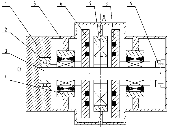
[0017] Such as figure 1 As shown, the outermost part of the present invention is an outer shell 5 and an end cap 1, and one axial end of the outer shell 5 is sealed and connected with the end cap 1, and a vacuum chamber is surrounded by the outer shell 5 and the end cap 1. In the middle of the inside of the vacuum chamber is the rotating shaft 3. The rotating shaft 3 has a common central axis with the outer shell 5 and the end cover 1. The central axis O of the rotating shaft 3 is also the outer shell 5, the end cover 1 and the central axis, that is, the entire flywheel battery of the central axis. The outer casing 5 is a rotationally symmetrical structure, the axis of rotational symmetry is the central axis O, the axial left and right symmetrical axis in the middle of the axial direction of the rotating shaft 3 is A, and the axial left and right symmetrical axis A and the central axis O intersect perpendicularly on the same radial section .

[0018] Inside the vacuum chambe...


PUM


Abstract

The invention discloses a flying wheel battery with a dual-flywheel structure. The exterior of the axial middle of a rotary shaft is coaxially sleeved with an axial winding structure with a gap; flying wheels, which are coaxially and fixedly arranged on the rotary shaft in a sleeving manner, are arranged on the left and right sides of the axial winding structure respectively; the two flying wheelsare symmetrically arranged left and right relative to the axial winding structure; bearingless permanent magnet motors, which are coaxially and fixedly arranged on the rotary shaft in a sleeving manner, are arranged on the left side of the left-side flying wheel and on the right side of the right-side flying wheel respectively; the two bearingless permanent magnet motors are symmetrically arranged left and right relative to the axial winding structure; 12 circular annular grooves are uniformly formed in the plate surfaces on the left and right sides of a circular plate iron core of the axialwinding structure in the circumferential direction; central cylinders are all wound with axial winding coils; inner and outer circular annular grooves are formed in the wheel surfaces on one sties ofthe flying wheels; annular permanent magnets are embedded in the corresponding circular annular grooves; by adopting one axial winding structure, the axial movement of the rotary shaft is limited; andcompared with a single-fly-wheel structured flying wheel battery with the same radius, the rotational inertia of the flying wheel battery with the dual-flywheel structure is two times of that of thesingle-fly-wheel structured flying wheel battery, so that the flying wheel battery with the dual-flywheel structure is higher in energy storage.

Description

technical field [0001] The invention relates to a magnetic levitation flywheel battery structure, which is suitable for fields such as space and military vehicles or as switching of uninterrupted power supplies. Background technique [0002] Flywheel battery is a new type of battery that breaks through the limitations of chemical batteries and utilizes physical energy storage. Utilizing the high quality of the flywheel so that it has a high moment of inertia, a large amount of kinetic energy can be stored and converted into electrical energy by the motor. Most traditional magnetic levitation flywheel batteries adopt a single flywheel structure, using two radial magnetic bearings and one axial magnetic bearing to provide levitation force, and charging and discharging are completed by two permanent magnet synchronous motors. Due to the large energy storage requirements of the flywheel battery, the flywheel needs a larger radius to increase its moment of inertia, which further...

Claims


Application Information

Patent Timeline
Patent Type & Authority Patents(China)
IPC IPC(8): H02K7/02
CPCH02K7/025Y02E60/16
Inventor 孙晓东金志佳陈龙杨泽斌李可
Owner JIANGSU UNIV
Why Eureka
Try Eureka