
Self-made heat conductor and heating equipment into which insulating heat conduction material is embedded and implementation method of self-made heat conductor and heating equipment

A technology of insulation and heat conduction and heat conductor, which is applied in the direction of cable installation, heating element shape, overhead installation, etc., and can solve the problems of high requirements and production costs

Pending Publication Date: 2018-08-03
SICHUAN UNIV +1
View PDF3 Cites 65 Cited by
  • Summary
  • Abstract
  • Description
  • Claims
  • Application Information

AI Technical Summary

Problems solved by technology

[0007] The purpose of the present invention is to provide a method of using insulating and heat-conducting materials instead of heating materials for the existing self-made heating wires embedded in heating materials, which re

Method used


Image

  • Self-made heat conductor and heating equipment into which insulating heat conduction material is embedded and implementation method of self-made heat conductor and heating equipment
  • Self-made heat conductor and heating equipment into which insulating heat conduction material is embedded and implementation method of self-made heat conductor and heating equipment
  • Self-made heat conductor and heating equipment into which insulating heat conduction material is embedded and implementation method of self-made heat conductor and heating equipment

Examples


Embodiment 1

[0093] The anti-icing and melting of ice is accomplished by using the power-transmitting heating equipment on the self-made thermal conductor embedded in the insulating and thermally conductive material.

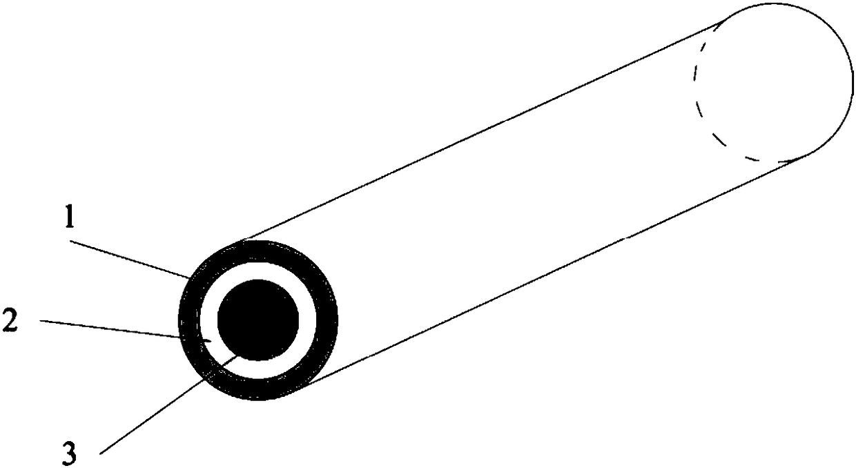
[0094] see attached figure 1 , 2 .

[0095] The self-made thermal conductor is a coaxial cable, including an outer conductor 1, an insulating and heat-conducting material 2 and an inner conductor 3; the insulating and heat-conducting material is a material with good heat conduction and insulating ability. This embodiment adopts the thermally conductive insulating material produced by Hefei AVIC Nanotechnology Development Co., Ltd.: Model: ZH-HCM-A.

[0096] The insulating and heat-conducting material 2 surrounds the outer side of the inner conductor, completely surrounds the outer periphery of the inner conductor, and completely isolates the inner and outer conductors to avoid short circuit of the inner and outer conductors. When alternating current or direct current is a...

Embodiment 2

[0160] The anti-icing and melting ice is completed by using the heating equipment at the power receiving end on the self-made thermal conductor embedded in the insulating and heat-conducting material.

[0161] See attached Figure 23 .

[0162] The heating equipment at the power receiving end is divided into two types: heating equipment using conventional transformers and heating equipment using anti-icing and ice-melting load transformers. In this embodiment, a heating device at the receiving end using a conventional transformer is used.

[0163] The heating equipment at the power receiving end that adopts a conventional transformer is composed of the fifth switch circuit 19-5, the sixth switch circuit 19-6, the power receiving microprocessor 72, the power receiving communication module 71, the power receiving conductor icing sensing module 73, steel Core load transformer 62 constitutes. The inner conductor and the outer conductor of the power transmission end are short-ci...

Embodiment 3

[0166] See attached Figure 24 .

[0167] This embodiment uses the heating equipment using the anti-icing and melting ice load transformer.

[0168]The heating equipment at the power receiving end adopting the anti-icing and melting load transformer is composed of the fifth switch circuit 19-5, the sixth switch circuit 19-6, the power receiving microprocessor 72, the power receiving communication module 71, and the power receiving conductor icing induction Module 73 is composed of anti-icing and melting ice-transmission load transformer 63. The inner conductor 3 and the outer conductor 1 of the power transmitting end are short-circuited and connected to the output of the power transmission power supply. The outer conductor 1 of the power receiving end is connected to the aluminum stranded wire winding of the anti-icing and melting load transformer 63, and the secondary winding of the anti-icing and melting load transformer 63 is connected to the electric load. The inner con...


PUM


Abstract

The invention discloses a self-made heat conductor and heating equipment into which an insulating heat conduction material is embedded and an implementation method of the self-made heat conductor andthe heating equipment. The self-made heat conductor is of a coaxial cable structure, and comprises an outer conductor, the insulating heat conduction material and an inner conductor. The insulating heat conduction material is good in heat conduction and has an insulating capability. The insulating heat conduction material surrounds the outer side of the inner conductor to completely surround the periphery of the inner conductor, so that the inner conductor and the outer conductor are completely isolated from each other. The heating equipment has the two types of sending-end heating equipment and receiving-end heating equipment. The sending-end heating equipment applies alternating current or direct current between the outer conductor and the inner conductor of the self-made heat conductorthrough an output power supply of an anti-icing and de-icing power transmission device to achieve the anti-icing and de-icing purpose, and the receiving-end heating equipment is connected with a loadthrough a receiving-end steel core to achieve the anti-icing and de-icing work. By means of the self-made heat conductor and heating equipment into which the insulating heat conduction material is embedded and the implementation method of the self-made heat conductor and the heating equipment, heating of steel core resistors of the self-made heat conductor and the heating equipment themselves is effectively utilized, the cost is low, and the effect is good. Under the control of a control center, the anti-icing and de-icing work is implemented and can be implemented online when a high voltage transmission line works, and the safety of electric equipment is guaranteed.

Description

1. Technical field [0001] The invention relates to the technical field of wire anti-icing and ice-melting, in particular to a self-made thermal conductor and heating equipment embedded with insulating and heat-conducting materials and a preparation method thereof. 2. Background technology [0002] In the cold winter, power and communication lines in many areas will freeze, causing damage to the lines. When the icing exceeds the bearing capacity of the line, serious accidents such as disconnection will occur. Therefore, deicing of power lines or other lines in winter is essential and very important. With the development of society and economy, the demand for national electric power and communication lines continues to increase. Under the environment of increasing power load applications, the requirements for exposed lines, especially power lines, are getting higher and higher. In the prior art, the wire melting technology continues to develop. However, the existing self-me...

Claims


Application Information

Patent Timeline
IPC IPC(8): H05B3/56H02G7/16
CPCH02G7/16H05B3/56
Inventor 莫思特谢和平刘天琪李碧雄
Owner SICHUAN UNIV
Learn More