Supercharge Your Innovation With Domain-Expert AI Agents!

Robot mounting arrangement

A surgical robot and equipment technology, applied in the field of robotic systems, can solve problems such as the limitation of the movement range of the mechanical arm, and the inability of the surgical assistant to move or reconfigure easily.

Active Publication Date: 2018-08-03
CMR SURGICAL LTD
View PDF14 Cites 2 Cited by
  • Summary
  • Abstract
  • Description
  • Claims
  • Application Information

AI Technical Summary

Problems solved by technology

However, for both approaches, the range of motion of the robotic arm is still limited such that a surgical assistant cannot easily move or reconfigure the walls to enable performing essentially any surgical procedure

Method used


Image

  • Robot mounting arrangement
  • Robot mounting arrangement
  • Robot mounting arrangement

Examples


Embodiment Construction

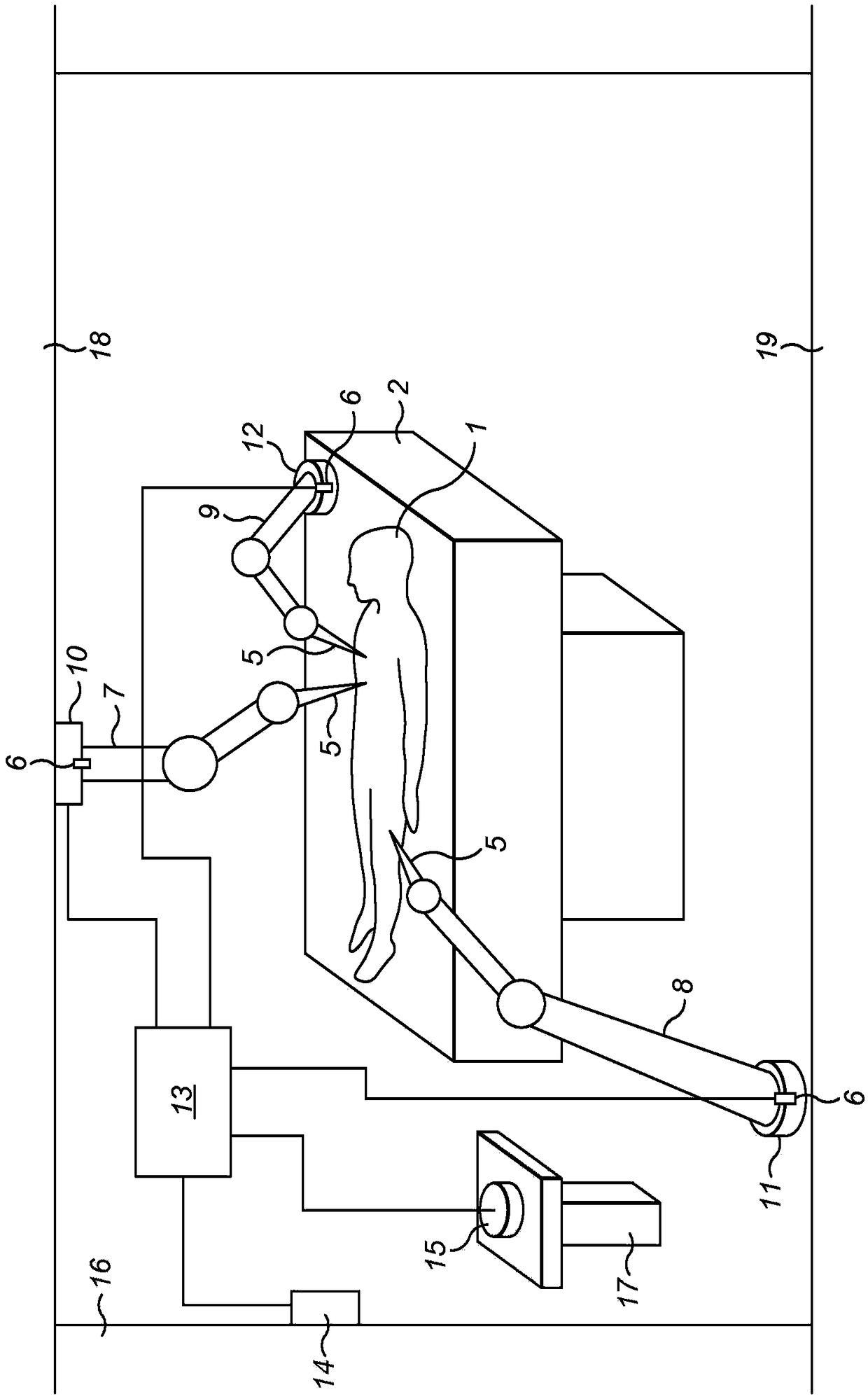
[0033] figure 1 A robotic system suitable for performing surgery on a patient 1 in an operating room is shown. The patient is on the hospital bed or on the operating table 2 . Each of the three robotic arms 7 , 8 and 9 has a proximal end configured to mate with one of the three mounting structures 10 , 11 and 12 . The mounting structures 10, 11 and 12 are fixedly attached to the ceiling 18, the floor 19 and the patient bed 2 of the operating room, respectively. Each arm is held in place in its respective mounting configuration by a manually operable latch mechanism 6 . The number of mounting structures in an operating room may be greater than the number of robotic arms. These robotic arms may cooperate with alternative mounting structures 14 and 15, here fixedly attached to the operating room wall 16 and base frame 17, respectively. The configuration of each mounting structure matches each other, and the configuration of the proximal end of each robotic arm matches each ot...


PUM


Abstract

A surgical robotic system comprises: a surgical robot arm (7, 8, 9) having at least six degrees of freedom, the arm having a distal end for attachment to a surgical tool (5) and a proximal end; and amounting structure (10, 11, 12) configured to mate to the proximal end of the arm for holding the proximal end of the arm spatially fixed. The mounting structure comprises an electrical connection part for powering the surgical robot arm, wherein the system comprises a manually operable latching mechanism (6) through which the arm can be attached to and released from the mounting structure.

Description

Background technique [0001] The invention relates to a robotic system, eg for performing surgical tasks. [0002] Robotic systems of various designs have been proposed to perform or assist surgical procedures. However, many robotic designs suffer from problems that make them unsuitable for performing a variety of different surgical procedures. [0003] Normally, a surgical robot has at least one robotic arm with a surgical tool attached to the distal end of the robotic arm. The pedestal supports the robot and the pedestal itself is attached to eg an operating room floor or a trolley. A robotic arm extends between the base and the tool. [0004] A robotic arm can have one or more degrees of freedom. Robotic arms typically have multiple articulations that are used to position the surgical tool in a desired position relative to the patient. For example, an arm may include one or more joints. These joints and tools may be able to be articulated to enable the robot to perform...

Claims


Application Information

Patent Timeline
IPC IPC(8): A61B90/57B25J9/00A61B34/30A61B90/50A61G13/10
CPCB25J9/0009B25J9/0018A61B2017/00477A61B90/50A61B34/30A61B2090/571A61G13/101A61B34/70A61B90/57B25J5/007B25J9/047B25J9/162
Inventor L·D·R·黑尔斯K·马歇尔
Owner CMR SURGICAL LTD
Features
  • R&D
  • Intellectual Property
  • Life Sciences
  • Materials
  • Tech Scout
  • Unparalleled Data Quality
  • Higher Quality Content
  • 60% Fewer Hallucinations
Learn More