
Synchronization Performance Evaluation Method of Synchronizer Ring

A technology of synchronizer rings and synchronization performance, which is applied in the testing of machines/structural components, instruments, clutches, etc., and can solve problems such as gear noise and slow synchronization

Active Publication Date: 2020-04-03
ISUZU MOTORS LTD
View PDF11 Cites 0 Cited by
  • Summary
  • Abstract
  • Description
  • Claims
  • Application Information

AI Technical Summary

Problems solved by technology

[0005] As for normal gear shifting, after the gears are synchronized with the synchronizer ring, the sleeve engages with the dogtooth of the gear, and the gear shifting is completed, but because if the synchronization of the synchronizer ring and the gears is slow, before the synchronization is completed , the adapter sleeve is inserted into the cogs of the gear, and contacts are made in a state where there is a rotation difference, which causes gear noise

Method used


Image

  • Synchronization Performance Evaluation Method of Synchronizer Ring
  • Synchronization Performance Evaluation Method of Synchronizer Ring
  • Synchronization Performance Evaluation Method of Synchronizer Ring

Examples


Embodiment Construction

[0029] In Japanese Patent Application No. 2015-006116 (invention name: method for manufacturing friction material of sliding parts and friction material thereof), the inventors of the present invention proposed a friction material with high porosity.

[0030] The friction material has a high porosity, can keep gear oil on the surface, and has good heat transfer performance, and the synchronization speed between the synchronizer ring and the gear is fast. It is used in the 16-speed transmission used on the above-mentioned large trucks. In the case of the synchronizer ring of the auxiliary transmission, it can be used as the best friction material.

[0031] Therefore, the inventors of the present invention focused on the gear oil formed on the surface of the friction material of the synchronizer ring for the reason why the synchronous speed increases when a friction material with a high porosity is used, and considered that the synchronous speed is affected by the gear oil formed...


PUM


Abstract

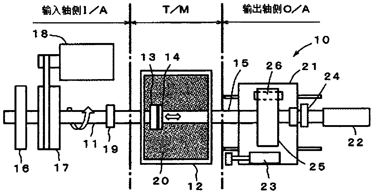
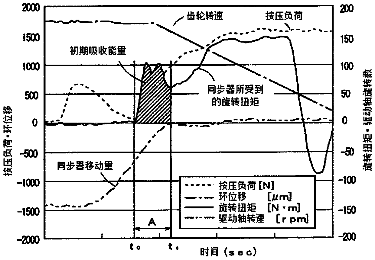
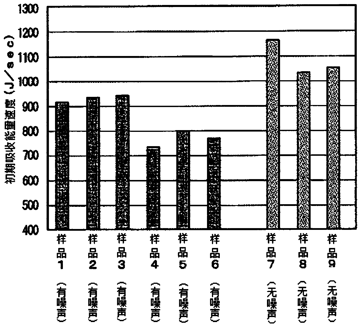
When evaluating the friction property of a synchronizer ring 14 by pressing the synchronizer ring 14 against a gear cone 13 in a synchro unit testing machine 10, the present invention finds the torque transmission force due to an oil film formed between the friction surface of the synchronizer ring 14 and gear cone surface prior to contact. As a method of finding the torque transmission force due to the oil film, the torque value and rotation rate during time (A) from after the generation of torque, prior to the synchro friction surface and the gear cone surface making contact, and until the contact with the gear cone, are integrated with respect to time to calculate the initial absorbed energy, which is divided by the time (A) to find the initial absorbed energy velocity. The synchronizer ring is evaluated by that initial absorbed energy velocity.

Description

technical field [0001] The present invention relates to a synchronization performance evaluation method of a synchronizer ring used when switching gear stages of a transmission of a vehicle. Background technique [0002] The 16-speed transmission used in large trucks has a 2-stage subtransmission of Hi and Low on the front side of the 4-stage main body, and a 2-stage range change (range change) of Hi and Low on the rear side. ×4×2=16 levels. Auxiliary transmissions Hi and Low use range changes to switch between even-numbered gears and odd-numbered gears, thereby switching between 1-8 speeds and 9-16 speeds. [0003] Because the driver is required to shift gears quickly so that the speed of the vehicle does not drop too much, the air drive will move the sleeve at a high speed for switching between the even and odd gears of the subtransmission. [0004] During this shift, the shafts and gears with different rotational speeds are in contact with the tapered surfaces of the ge...

Claims


Application Information

Patent Timeline
Patent Type & Authority Patents(China)
IPC IPC(8): G01M13/025F16D23/06
CPCF16D23/06G01M13/02
Inventor 石上英征竹田敏和
Owner ISUZU MOTORS LTD
Learn More