
Full-automatic relay calibration device and method

A technology of calibration devices and relays, applied in the field of electric power, can solve problems such as difficult connection of test equipment, poor wiring contact, short circuit, etc.

Pending Publication Date: 2020-10-23
JIANGSU NUCLEAR POWER CORP
View PDF0 Cites 0 Cited by
  • Summary
  • Abstract
  • Description
  • Claims
  • Application Information

AI Technical Summary

Problems solved by technology

[0003] There are many disadvantages in the traditional method. For example, the number of relays to be calibrated is huge, and it takes too long to calibrate each relay by this method; the wiring of relay terminals is very dense, and it is difficult to connect the test equipment, which is prone to accidental touches, resulting in short circuits and damage to the relays. Inspection equipment; due to factors such as manual wiring, poor wiring contact, and wrong terminal connection, the calibration data is inaccurate, etc.

Method used


Image

  • Full-automatic relay calibration device and method
  • Full-automatic relay calibration device and method
  • Full-automatic relay calibration device and method

Examples


Embodiment Construction

[0033] Below in conjunction with embodiment and accompanying drawing, the present invention is further described:

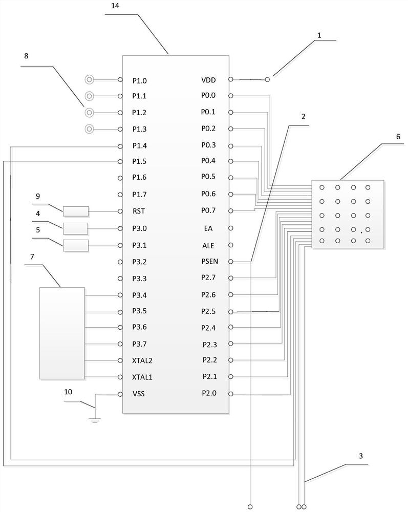
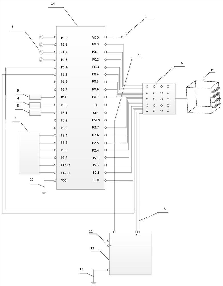
[0034] like figure 1 As shown, a fully automatic relay verification device provided by the present invention includes a power supply 1, a communication interface 2, an external input voltage interface 3, a start button 4, a stop button 5, a plug-in module 6, a display 7, and an indicator light 8. A reset button 9 , a grounding module 10 and a single-chip microcomputer 14 .

[0035] The external +5V voltage is connected to the power supply 1;

[0036] The start button 4 is connected to the microcontroller pin P3.0, which is valid when reading the high level of the external microcontroller pin P3.0;

[0037] The stop button 5 is connected to the pin P3.1 of the single-chip microcomputer, and it is valid when reading the high level of the pin P3.1 of the external single-chip microcomputer;

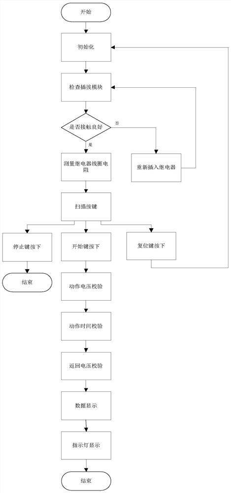
[0038] There are 20 jacks in the plug-in module 6, and 18 pins are conne...


PUM


Abstract

The invention belongs to the technical field of power and particularly relates to a full-automatic relay calibration device and method. The device comprises a power supply, a communication interface,an external input voltage interface, a start button, a stop button, a plugging module, a display, an indicating lamp, a reset button, a grounding module and a single-chip microcomputer, wherein the power supply, the communication interface, the start button, the stop button, the plugging module, the display, the indicating lamp, the reset button and the grounding module are respectively connectedwith the single-chip microcomputer, and the other end of the plugging module is connected with the external input voltage interface. The device is advantaged in that the node state indicating lamp isadded, so the relay node quality can be directly, rapidly and obviously judged in the test process; the communication interface is communicated with the relay protection tester, so functions of automatic voltage increase and decrease, timing check, action time check and the like are realized, and data is directly displayed on the display; the chip is adopted to replace a traditional manual measurement and calculation step, a coil resistance value can be displayed through the device, and manpower and material resources are saved.

Description

technical field [0001] The invention belongs to the technical field of electric power, and in particular relates to a fully automatic relay calibration device and method. Background technique [0002] Relays are used to control electrical equipment in circuits and can transmit intermediate signals in control circuits. In simple terms, it is an electrical signal transmission device, which plays the role of conversion circuit, automatic adjustment and safety protection. In different control circuits, the function of the relay is different. It consists of a fixed iron core, a moving iron core, a spring, a moving contact, a static contact, a coil, a terminal and a casing. The coil sensitivity of the electromagnetic relay may decrease after being used for a period of time, and the relay needs to be calibrated. The conventional calibration method is to first use a multimeter to measure the coil resistance, and then use a relay protection tester to provide the relay with an operat...

Claims


Application Information

Patent Timeline
IPC IPC(8): G01R31/327
CPCG01R31/3278
Inventor 朱永乐孟凡博王静涛贾杰邹晓王欣高威黄昌军张轩王波苏亚萍张亚军李栋车鹏赵思媛
Owner JIANGSU NUCLEAR POWER CORP
Learn More