
Improved vehicle-mounted electronic equipment

An in-vehicle electronic and improved technology, applied in vehicle components, circuits or fluid pipelines, transportation and packaging, etc., can solve problems such as poor power supply safety, damage to brackets or brackets, and threats to the safety of people on the vehicle, and achieve convenient operation. , the effect of simple structure

Inactive Publication Date: 2018-08-07
广州程科电子科技有限公司
View PDF5 Cites 0 Cited by
  • Summary
  • Abstract
  • Description
  • Claims
  • Application Information

AI Technical Summary

Problems solved by technology

The structure design of ordinary frame on the market usually uses hooks and buckles to fix various improved on-board electronic devices, so that various improved on-board electronic devices with different models and sizes can be used. However, once the car encounters an emergency Under certain conditions, such as braking, acceleration, and collision, the brackets or brackets used to fix the improved on-board electronic equipment are easily damaged, so that the improved on-board electronic equipment will fly off the bracket or bracket, directly threatening the safety of the occupants of the vehicle , and the safety of power supply is poor, therefore, there is an urgent need for an improved vehicle-mounted electronic device that is convenient and quick to disassemble and secure power supply

Method used


Image

  • Improved vehicle-mounted electronic equipment
  • Improved vehicle-mounted electronic equipment
  • Improved vehicle-mounted electronic equipment

Examples


Embodiment Construction

[0014] Combine below Figure 1-Figure 4 The present invention will be described in detail.

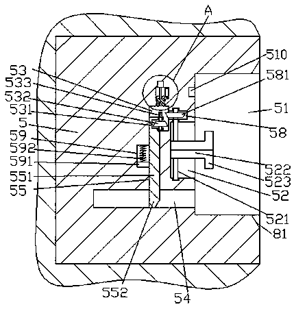
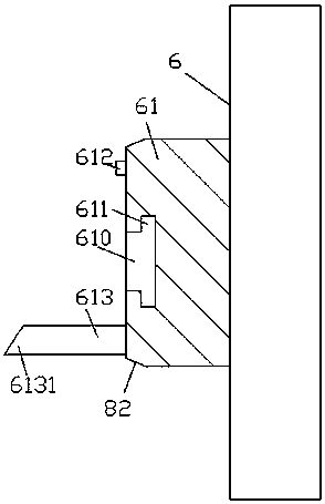
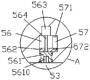
[0015] refer to Figure 1-Figure 4 , an improved vehicle-mounted electronic device according to an embodiment of the present invention, including a mounting base body 5 fixedly installed in the vehicle body and an electronic equipment body 6 for mating connection with the mounting base body 5, the mounting base body 5. An insertion groove 51 is provided in the right end surface, and a guide groove 52 is provided in the left inner wall of the insertion groove 51, and a guide groove 52 is provided in the left inner wall of the insertion groove 51 on the lower side of the guide groove 52. The push chute 54 extending to the left side, the inner wall of the mounting seat body 5 on the left side of the guide chute 52 is provided with a linkage slide cavity 53, and the linkage slide cavity 53 and the push chute 54 A connecting rod through groove 55 is arranged between them, and a C-shaped c...


PUM


Abstract

Provided is improved vehicle-mounted electronic equipment. The equipment comprises a mounting seat body fixedly arranged in a vehicle body and an electronic equipment machine body used for being in cooperative connection with the mounting seat body, a mounting insertion groove is formed in the right side end face of the mounting seat body, a guide sliding groove is formed in the inner wall of theleft side of the mounting insertion groove, a pushing sliding groove extending to the left side is formed in the inner wall of the left side of the mounting insertion groove at the lower side of the guide sliding groove, a linkage sliding cavity is formed in the inner wall body of the mounting seat body at the left side of the guide sliding groove, a connecting rod through groove is communicated with the portion between the linkage sliding cavity and the pushing sliding groove, the linkage sliding cavity is internally and slidably in cooperative connection with a C-shaped sliding frame, the C-shaped sliding frame is internally and rotationally in cooperative connection with a first cone pulley, the top end of the C-shaped sliding frame is provided with an external spline shaft in dynamic and cooperative connection with the first cone pulley, the connecting rod through groove is internally and slidably in cooperative connection with a sliding connection rod, and the tail end of the topof the sliding connection rod is fixedly connected with the tail end of the bottom of the C-shaped sliding frame.

Description

technical field [0001] The invention relates to the technical field of vehicle equipment, in particular to an improved vehicle electronic equipment. Background technique [0002] More and more car users choose to install and use various improved in-vehicle electronic devices in the car, such as tablet computers, DVD players, multimedia players, etc. to fix. The structure design of ordinary frame on the market usually uses hooks and buckles to fix various improved on-board electronic devices, so that various improved on-board electronic devices with different models and sizes can be used. However, once the car encounters an emergency Under certain conditions, such as braking, acceleration, and collision, the brackets or brackets used to fix the improved on-board electronic equipment are easily damaged, so that the improved on-board electronic equipment will fly off the bracket or bracket, directly threatening the safety of the occupants of the vehicle , and the power supply...

Claims


Application Information

Patent Timeline
Patent Type & Authority Applications(China)
IPC IPC(8): B60R11/02B60R16/02
CPCB60R11/02B60R16/02
Inventor 韦健杭吴敏俊
Owner 广州程科电子科技有限公司
Learn More