Voice coil for soundbox with radiating function

A voice coil and audio technology, applied in the direction of electrical components, sensors, etc., can solve the problems of reducing the service life of the audio, affecting the life of the speaker, loose voice coil coils, etc., to prolong the service life, improve convenience and stability, and improve the use of The effect of longevity

Inactive Publication Date: 2018-08-07
安远兴美电子有限公司
View PDF7 Cites 2 Cited by
  • Summary
  • Abstract
  • Description
  • Claims
  • Application Information

AI Technical Summary

Problems solved by technology

[0002] Nowadays, with the improvement of living standards and technology, audio products are widely used in business and family life, and the sound components of audio products are generally loudspeakers. Generally, when the loudspeaker is working, high-frequency current passes through the voice coil The coil generates a magnetic field, which drives the speaker cone to vibrate. Since the current passes through the voice coil coil to generate a magnetic field, the heating of the voice coil coil cannot be avoided. The high temperature caused by excessive power is likely to cause a series of failures of the speaker and also affect the life of the speaker. , so the heating of the coil is the main reason why the power of the speaker cannot be increased. The high temperature requires a larger structural space for the speaker to avoid slow heat dissipation, which leads to a limitation of the overall height of the speaker, which cannot meet the design needs of a thin speaker. It affects the sound quality of the speaker, and also reduces the service life of the speaker. At the same time, because of frequent high-speed vibration, it is easy to cause the voice coil coil to loosen, and the number of coil turns is disordered or broken, which greatly reduces the service life.

Method used


Image

  • Voice coil for soundbox with radiating function
  • Voice coil for soundbox with radiating function
  • Voice coil for soundbox with radiating function

Examples


Embodiment Construction

[0018] The following will clearly and completely describe the technical solutions in the embodiments of the present invention with reference to the accompanying drawings in the embodiments of the present invention. Obviously, the described embodiments are only some, not all, embodiments of the present invention. Based on the embodiments of the present invention, all other embodiments obtained by persons of ordinary skill in the art without making creative efforts belong to the protection scope of the present invention.

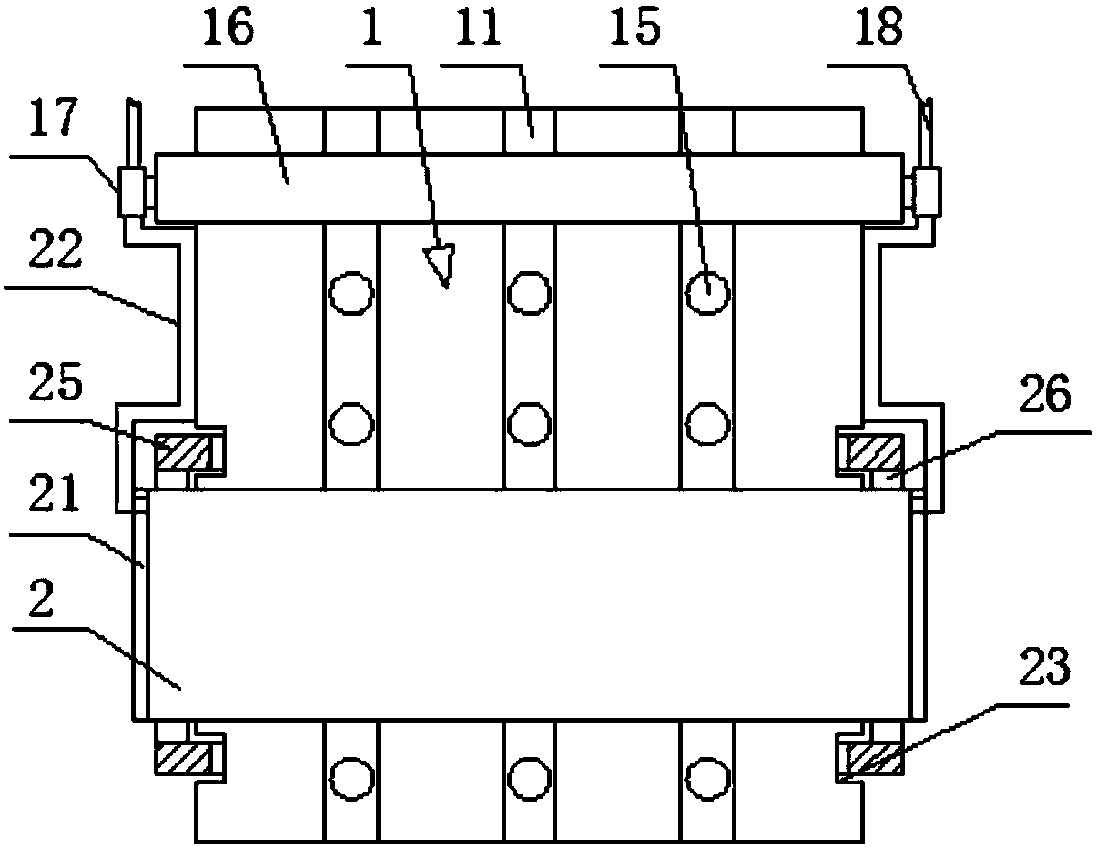
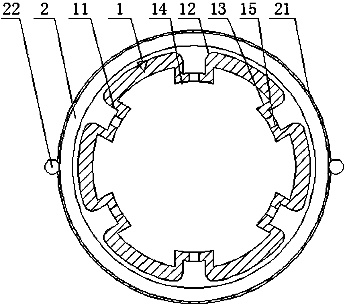
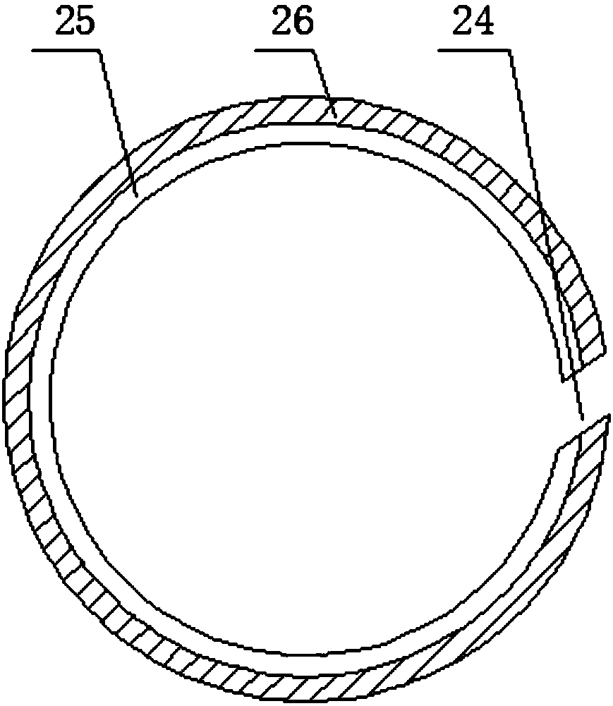
[0019] see Figure 1-4 , the present invention provides a technical solution: a voice coil for audio with heat dissipation function, comprising a voice coil bobbin 1, and the voice coil bobbin 1 includes a kraft paper layer 101, an asbestos paper layer 102, a varnish cloth layer 103 and a 303 aluminum sheet layer 104 , the outer surface of the kraft paper layer 101 is fixedly adhered with an asbestos paper layer 102, the outer surface of the asbestos paper lay...


PUM

PropertyMeasurementUnit
Thicknessaaaaaaaaaa

Abstract

The invention discloses a voice coil for a soundbox with a radiating function. The voice coil for the soundbox comprises a voice coil framework, an avoidance groove is arranged on an outer surface ofthe voice coil framework, avoidance round corners are arranged at two end surfaces of the avoidance groove; a connecting bar is fixedly connected with an internal surface of the avoidance groove, an arc binding face is arranged on the inside surface of the connecting bar, and air vents are arranged at the internal center of the arc binding face. The voice coil for the soundbox with the radiating function can guarantee the stability of the voice coil in combination with an elastic check ring and an annular check rail in clamping through the voice coil framework structure in multilayer structure, the disorder of the turns per coil is avoided, and the service life is improved; the radiating area of partial coil can be indirectly increased by combining the avoidance groove with the air vents,the radiating effect is improved, the excess temperature in use is avoided, the convenience and stability of the use are greatly improved, the radiating efficiency is guaranteed, the service life is prolonged, and the use cost is reduced.

Description

technical field [0001] The invention relates to the field of audio technology, in particular to a voice coil for audio with heat dissipation function. Background technique [0002] Nowadays, with the improvement of living standards and technology, audio products are widely used in business and family life, and the sound components of audio products are generally loudspeakers. Generally, when the loudspeaker is working, high-frequency current passes through the voice coil The coil generates a magnetic field, which drives the speaker cone to vibrate. Since the current passes through the voice coil coil to generate a magnetic field, the heating of the voice coil coil cannot be avoided. The high temperature caused by excessive power is likely to cause a series of failures of the speaker and also affect the life of the speaker. , so the heating of the coil is the main reason why the power of the speaker cannot be increased. The high temperature requires a larger structural space ...

Claims


Application Information

Patent Timeline
IPC IPC(8): H04R9/02H04R9/04
CPCH04R9/022H04R9/046
Inventor 韩双益
Owner 安远兴美电子有限公司
Why Eureka
Try Eureka