Additive and subtractive composite forming equipment and machining method

A technology of composite molding, adding and subtracting materials, applied in the direction of additive processing, other manufacturing equipment/tools, additive manufacturing, etc., can solve the problems of limited precision, difficulty in maintaining the original position, fluctuation of thickness and height of metal parts, etc., and achieve improved processing The effect of quality and efficiency, avoiding the step effect, and fast processing speed

Inactive Publication Date: 2018-08-10
GUANGDONG HANS YUEMING LASER GRP CO LTD +2
View PDF9 Cites 3 Cited by
  • Summary
  • Abstract
  • Description
  • Claims
  • Application Information

AI Technical Summary

Problems solved by technology

However, when laser fusion forming technology is used for processing, a layer of dense and hard irregular outer layer flows on the surface of the part. There is an obvious step effect on the surface of the part, and the flatness and finish are not high. The resulting metal parts are difficult to process Post-processing, resulting in large problems in the accuracy and surface quality of the obtained parts, which seriously affects the widespread promotion and application of this 3D printing technology in the precision parts manufacturing industry
[0003] At present, the mainstream laser nozzles in the market mostly use multi-channel coaxial light to send powder outside, and adopt the structure of multi-layer powder road ring surrounding the laser beam. In laser rapid prototyping, the light incident route of the powder is the oblique throwing movement route. , the metal powder is obliquely thrown into the laser molten pool, the powder spots converge and are not easy to keep in place, which limits the further improvement of its precision in the part manufacturing process
At the same time, multi-channel coaxial powder cannot completely eliminate the problem of directionality. When the direction of the laser scanning track changes, the amount of powder cladding will change, resulting in large fluctuations in the thickness and height of the formed metal parts, making it difficult to ensure uniformity , this kind of fluctuation cannot be eliminated in the subsequent accumulation, forming the accumulation of errors

Method used


Image

  • Additive and subtractive composite forming equipment and machining method
  • Additive and subtractive composite forming equipment and machining method
  • Additive and subtractive composite forming equipment and machining method

Examples


Embodiment Construction

[0019] In order to further understand the features, technical means, and specific objectives and functions achieved by the present invention, the present invention will be further described in detail below in conjunction with the accompanying drawings and specific embodiments.

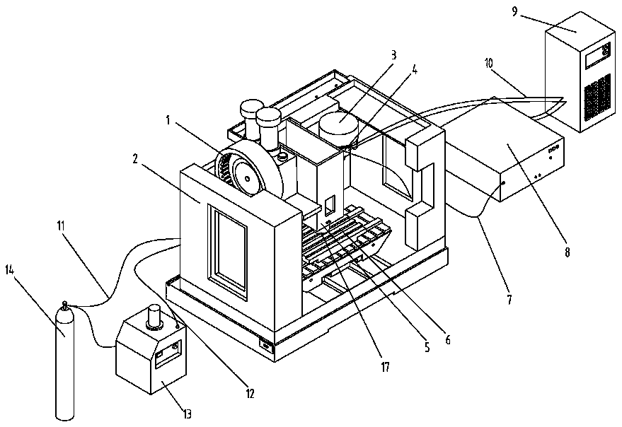
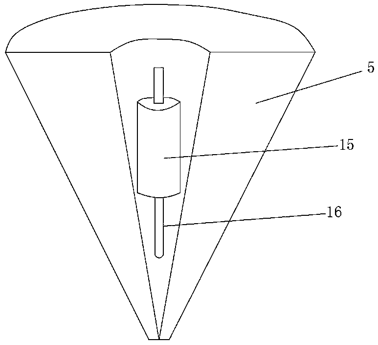
[0020] as attached figure 1 and 2 As shown, the present invention discloses a compound molding equipment for adding and subtracting materials, including a cabinet 2, a workbench 6 is arranged inside the cabinet 2, an XY-axis moving mechanism is arranged on the bottom surface of the workbench 6, and a spindle 5 is arranged inside the cabinet 2, The main shaft 5 is connected with the driver, and the driver drives the main shaft to move up and down in the Z-axis direction. The subtractive molding tool magazine 1 is installed on the left side of the main shaft 5, and the additive molding tool magazine 3 and powder feeding laser are installed on the right side of the main shaft 5. Nozzle 4, the lower end o...


PUM


Abstract

The invention provides additive and subtractive composite forming equipment and a machining method. The additive and subtractive composite forming equipment comprises a machine box, wherein a workbench is arranged in the machine box, an XY-axis moving mechanism is arranged on the bottom surface of the workbench, a main shaft is arranged in the machine box, the main shaft is connected with a driver, a subtractive forming tool library is arranged on the left side of the main shaft, the right side of the main shaft is provided with an additive forming tool library and a powder feeding laser nozzle, the lower end of the main shaft is provided with a working head, the powder feeding laser nozzle is connected with a laser through a laser optical fiber, the powder feeding laser nozzle is connected with the powder feeding device through a powder feeding tube, the laser powder feeder is connected with the protective gas supply device through a pipeline, and the protective gas supply device is connected with the powder feeding laser nozzle through an air pipe. According to the additive and subtractive composite forming equipment, the efficiency of rapid forming machining and cutting machining is improved, and the machining quality is improved.

Description

technical field [0001] The invention relates to a compound molding equipment and processing method of increasing and decreasing materials. Background technique [0002] Laser fusion rapid prototyping technology retains a series of advantages such as traditional 3D printing, which can realize flexible design and manufacturing, reduce the cost and cycle of product development and manufacturing, and can form complex structural parts at one time. At the same time, compared with other 3D printing technologies for metal parts, the parts formed by laser melting rapid prototyping technology are larger in size, faster in forming speed and higher in powder utilization. However, when laser fusion forming technology is used for processing, there is a layer of dense and hard irregular outer layer flowing on the surface of the part, and there is an obvious step effect on the surface of the part, and the flatness and finish are not high. Post-processing, resulting in large problems in the...

Claims


Application Information

Patent Timeline
Patent Type & Authority Applications(China)
IPC IPC(8): B22F3/105B23P23/00B33Y30/00
CPCB23P23/00B33Y30/00B22F10/00B22F12/33B22F10/25B22F12/70B22F12/53B22F12/20B22F10/50B22F10/322B22F10/80Y02P10/25
Inventor 李游马敬奇周广兵旷雅胜王楠胡小虎
Owner GUANGDONG HANS YUEMING LASER GRP CO LTD
Why Eureka
Try Eureka