Automatic ignition type welding and cutting torch

An automatic ignition, welding and cutting technology, which is applied in the field of welding torches and cutting torches, can solve the problems of burns of ignition personnel, falling of people or objects, difficulty in igniting, etc., and achieve the effect of avoiding burn hazards

Pending Publication Date: 2018-08-10
徐慕庆
View PDF0 Cites 2 Cited by
  • Summary
  • Abstract
  • Description
  • Claims
  • Application Information

AI Technical Summary

Problems solved by technology

[0002] The traditional welding torch or cutting torch is usually ignited by an external fire source, such as a lighter or a match, which may cause burns to the igniter when ignited, and when operating outdoors, due to strong wind large, hard to light
When working at high altitude, holdi

Method used


Image

  • Automatic ignition type welding and cutting torch
  • Automatic ignition type welding and cutting torch
  • Automatic ignition type welding and cutting torch

Examples


Embodiment Construction

[0017] The present invention will be described in further detail below in conjunction with the accompanying drawings.

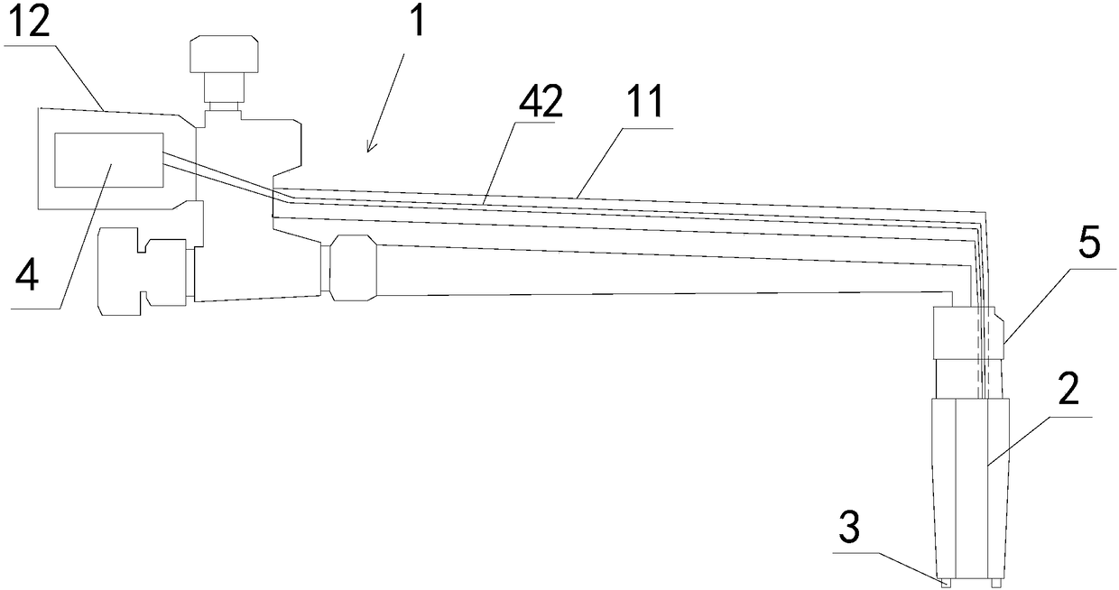
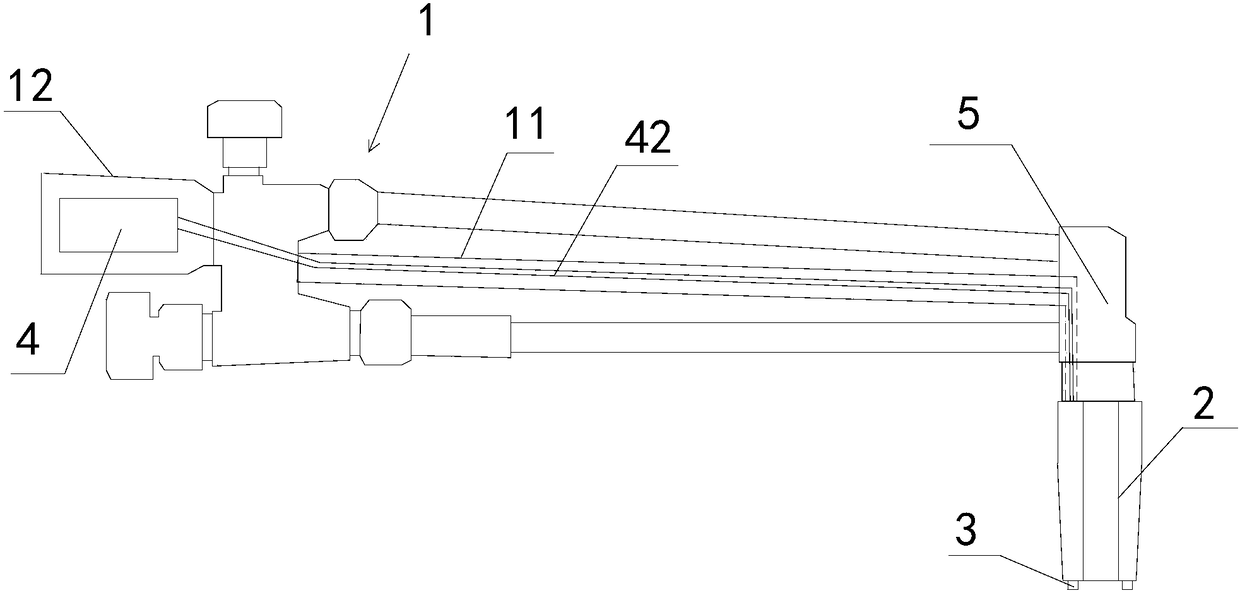
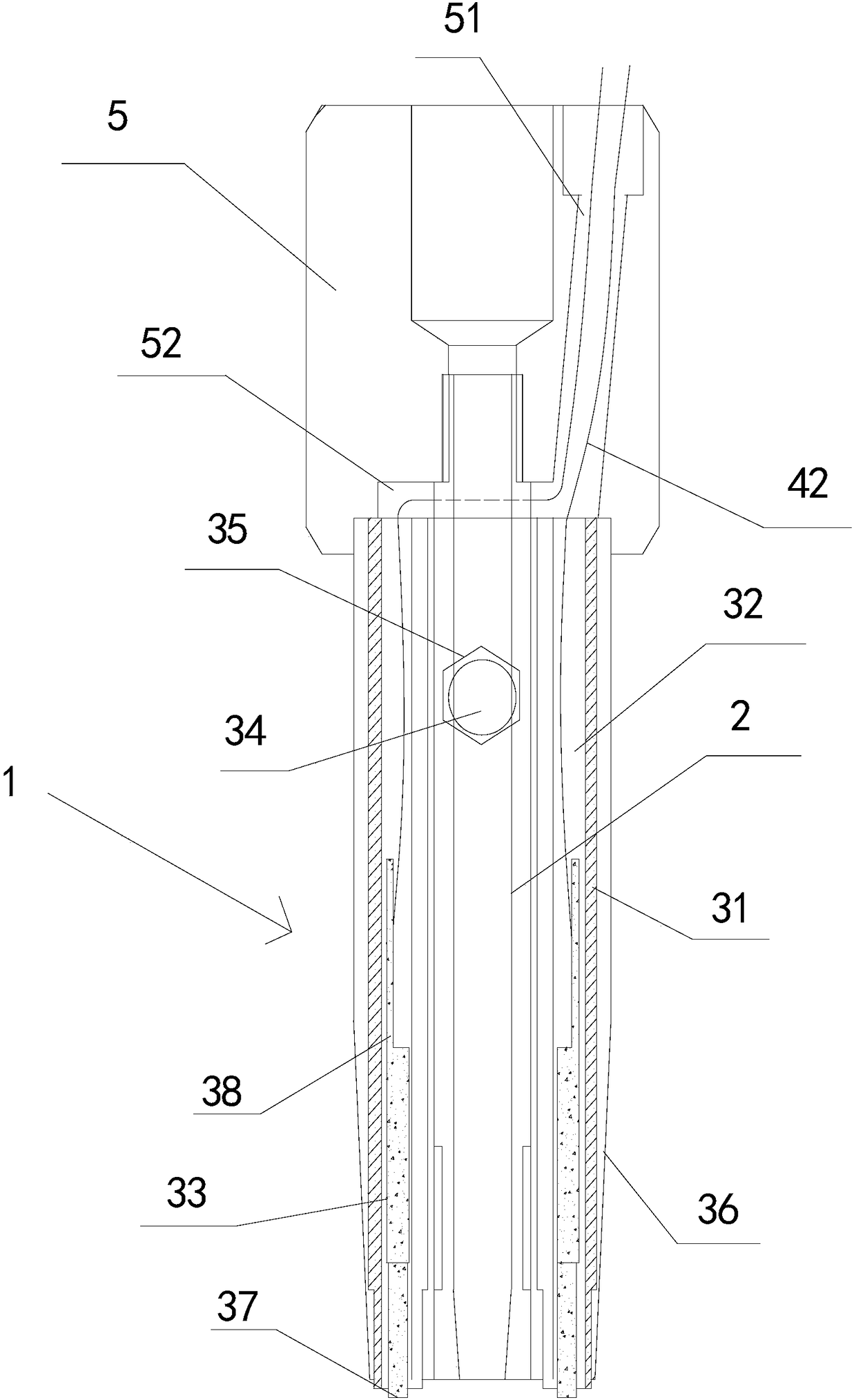
[0018] Such as Figure 1-3 As shown, an automatic ignition type welding and cutting torch includes a torch body 1, a torch nozzle 2, an ignition device 3 and a DC discharge device 4 arranged on the torch body 1. Wherein, the torch body 1 may be a torch body of a welding torch, and the torch nozzle 2 may be a torch nozzle of a torch. In addition, the gun body 1 can also be a cutting gun body, and the gun nozzle 2 can also be a cutting gun nozzle. The output end of the gun body 1 is provided with a gun mouth connecting thread 5 , wherein the gun mouth connecting thread 5 can be a welding torch mouth connecting thread or a cutting torch mouth connecting thread.

[0019] The gun mouth 2 is arranged on the gun mouth connecting thread 5 . In this embodiment, the threaded hole is drilled at the end where the gun nozzle connecting thread 5 is connected to the gun ...


PUM


Abstract

The invention discloses an automatic ignition type welding and cutting torch. The automatic ignition type welding and cutting torch comprises a torch body, a torch nozzle, an ignition device and a direct current discharge device arranged on the torch body. The output end of the torch body is provided with a torch nozzle connection screw thread, and the torch nozzle is arranged on the torch nozzleconnection screw thread. The ignition device comprises an insulating tube arranged on the torch nozzle in a sleeving mode, and first penetrating holes are separately formed in the two opposite side walls of the insulating tube. The axes of the first penetrating holes are parallel to the axis of the insulating tube, and the first penetrating holes are internally provided with spray points. The positive and negative poles of the direct current discharge device are separately and electrically connected to the spray points through wires in a one-to-one correspondence mode, and the spray points candischarge and ignite at one end, away from the torch nozzle connection screw thread, of the torch nozzle. By arranging an insulator, the spray points is insulated from the torch body and the torch nozzle, and the two spray points separately serve as the positive and negative poles of the direct current discharge device, so that electric sparks can be generated between the two spray points for ignition, the ignition can avoid the burn hazard to operators, and the ignition can still be smoothly performed in the case of strong wind outside.

Description

technical field [0001] The invention relates to a welding torch and a cutting torch, in particular to an automatic ignition type welding and cutting torch. Background technique [0002] The traditional welding torch or cutting torch is usually ignited by an external fire source, such as a lighter or a match, which may cause burns to the igniter when ignited, and when operating outdoors, due to strong wind Big and hard to light. When working at high altitude, holding a welding torch or cutting torch in one hand and igniting the fire in the other will also cause the danger of people or objects falling, or when working in special places, it is impossible to bring a fire source such as a lighter into it, causing problems such as inability to work. Contents of the invention [0003] The object of the present invention is to provide an automatic ignition type welding and cutting torch to solve one or more of the above-mentioned problems in the prior art. [0004] According to ...

Claims


Application Information

Patent Timeline
IPC IPC(8): B23K5/00B23K5/22B23K7/00B23K7/10
CPCB23K5/00B23K5/22B23K7/00B23K7/10
Inventor 徐慕庆
Owner 徐慕庆
Why Eureka
Try Eureka