
Electronic automatic internal ignition device of cutting torch

An ignition device and cutting torch technology, applied in the field of cutting torches, can solve the problems of burns, inability to work, and difficulty in igniting ignition personnel, and achieve the effect of avoiding burn hazards.

Pending Publication Date: 2017-05-31
徐慕庆
View PDF10 Cites 6 Cited by
  • Summary
  • Abstract
  • Description
  • Claims
  • Application Information

AI Technical Summary

Problems solved by technology

[0002] The traditional torch is usually ignited by an external fire source, such as a lighter or a match, which may cause burns to the igniter when it is ignited, and when it is operated outdoors, due to the strong wind, difficult to light a fire
When working at heights, holding a torch in one hand and igniting the fire in the other will also cause the danger of people or objects falling, or when working in special places, it is impossible to bring a fire source such as a lighter into it, resulting in problems such as inability to work

Method used


Image

  • Electronic automatic internal ignition device of cutting torch
  • Electronic automatic internal ignition device of cutting torch
  • Electronic automatic internal ignition device of cutting torch

Examples


Embodiment 2

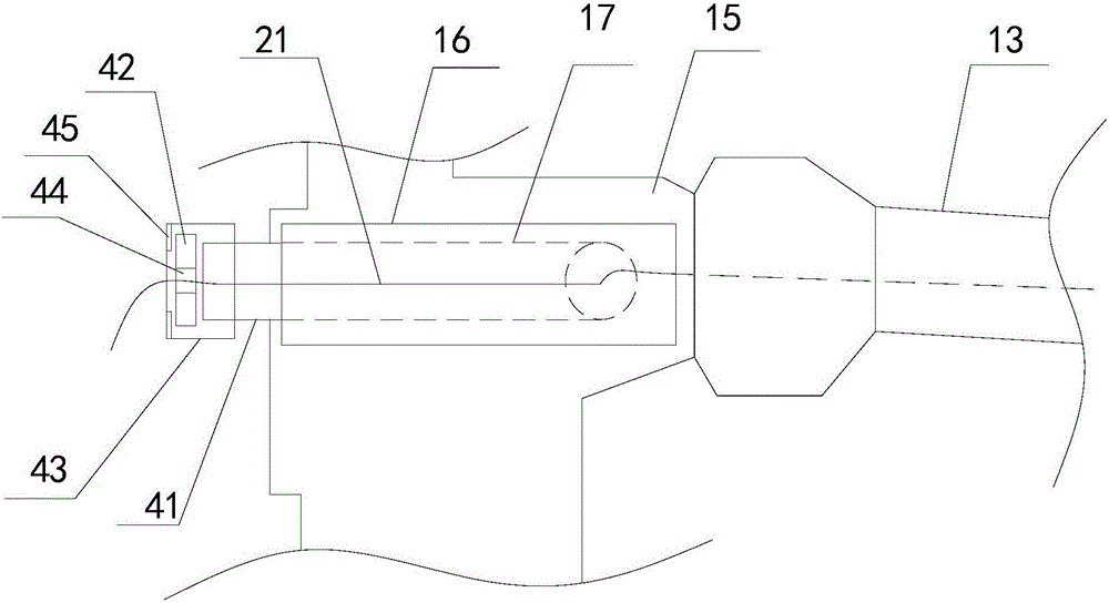
[0022] Embodiment two, such as image 3 As shown, the torch body 1 can also include an oxygen valve 15, the oxygen valve 15 is located between the handle 11 and the oxygen pipe 13, the side wall of the oxygen valve 15 is integrally formed with a thickened part 16, and a supply wire can be opened in the thickened part 16 21 through the third perforation 17, one end of the third perforation 17 communicates with the end of the oxygen valve 15 close to the oxygen pipe 13, the other end of the third perforation 17 is used for the penetration of the wire 21 and is provided with a sealing device, the sealing device can seal the third The perforation 17 is sealed to prevent air leakage. In this way, the wire 21 passes through the fourth through hole 12 of the handle 11 and then passes through the third through hole 17 , crosses the oxygen valve 15 and enters into the oxygen tube 13 . And oxygen pipe 13, converging head 14 and cutting nozzle 3 are all interlinked, therefore, lead wire...


PUM


Abstract

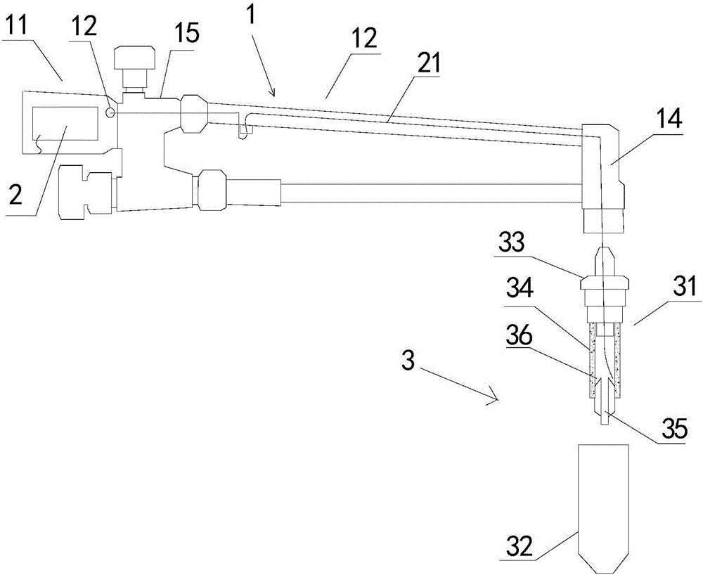
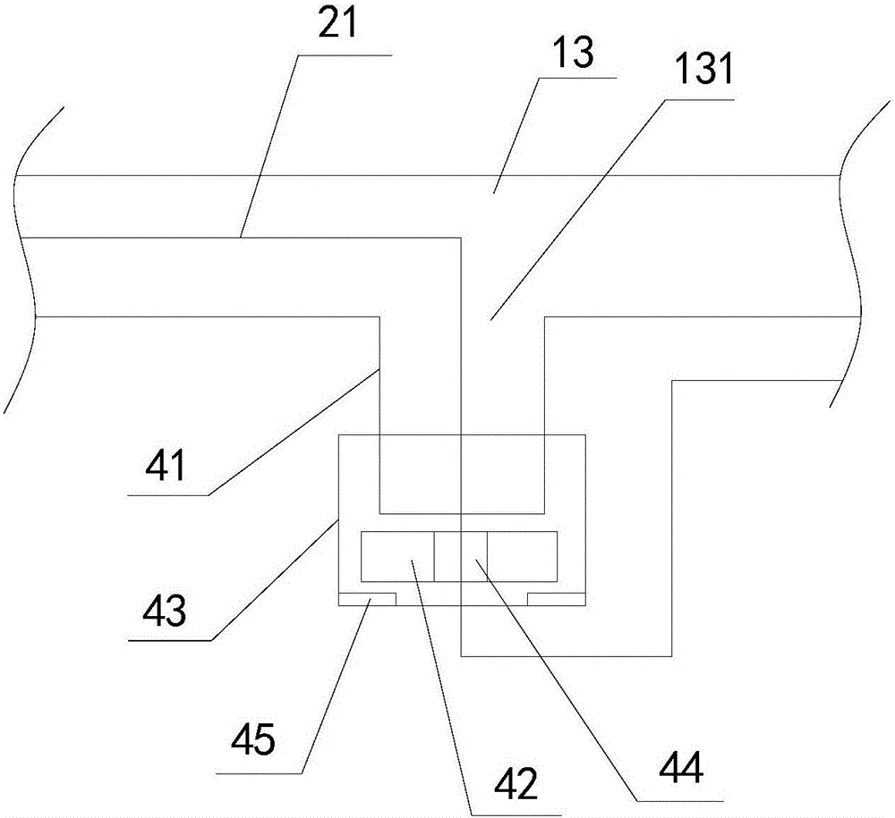
The invention discloses an electronic automatic internal ignition device of a cutting torch. The electronic automatic internal ignition device of the cutting torch comprises a cutting torch body, a cutting nozzle and a direct current discharge device arranged on the cutting torch body. The cutting nozzle comprises a nozzle core and a nozzle cap sleeving the nozzle core. The nozzle core comprises a nozzle cap connecting threaded port, an insulator and an oxygen outlet nozzle which are connected in sequence. One electrode of the direct current discharge device is electrically connected with the oxygen outlet nozzle, the other electrode of the direct current discharge device is electrically connected with the nozzle cap, and electric sparks can be generated between the nozzle cap and the oxygen outlet nozzle. By arranging the insulator, insulation between the oxygen outlet nozzle and the cutting torch body is achieved, and the insulator serves as one electrode of the direct current discharge device. The nozzle cap serves as the other electrode of the direct current discharge device, discharge between the oxygen outlet nozzle and the nozzle cap is achieved, and electric sparks are generated for ignition. Through the ignition mode, burning injuries to an operator can be avoided, and ignition can be conducted smoothly under the condition of outdoor strong wind.

Description

technical field [0001] The invention relates to a torch, in particular to an electronic automatic internal ignition device of the torch. Background technique [0002] The traditional torch is usually ignited by an external fire source, such as a lighter or a match, which may cause burns to the igniter when it is ignited, and when it is operated outdoors, due to the strong wind, Difficult to light a fire. When working at high altitudes, holding a torch in one hand and igniting the fire in the other will also cause the danger of people or objects falling, or when working in special places, it is impossible to bring fire sources such as lighters into it, resulting in problems such as inability to work. Contents of the invention [0003] The object of the present invention is to provide an electronic automatic internal ignition device of a torch, which can solve one or more of the above-mentioned problems in the prior art. [0004] According to one aspect of the present inve...

Claims


Application Information

Patent Timeline
Patent Type & Authority Applications(China)
IPC IPC(8): F23Q3/00F23D14/42
CPCF23D14/42F23Q3/00
Inventor 徐慕庆
Owner 徐慕庆
Learn More