
Battery pack system

A battery pack and battery box technology, which is applied in the field of battery pack systems, can solve problems such as damage to the battery box, affect battery performance, and increase battery internal pressure, and achieve enhanced cooling effects, avoiding burning hazards, and less demand.

Active Publication Date: 2014-07-23
MICROVAST POWER SYST CO LTD
View PDF7 Cites 3 Cited by
  • Summary
  • Abstract
  • Description
  • Claims
  • Application Information

AI Technical Summary

Problems solved by technology

[0003] As the main energy storage device of electric vehicles, the battery cell is generally formed by connecting multiple batteries in series and parallel. During the charging process of the lithium-ion battery, the aprotic solvent in the electrolyte will react on the interface between the electrode and the electrolyte. These reactions On the one hand, a passivation film covering the electrode surface is formed, and at the same time, gases such as hydrogen, hydrocarbons, carbon monoxide, and carbon dioxide are generated. These gases will increase the internal pressure of the battery and cause gas swelling, which will seriously affect the performance of the battery. Cycle performance and battery safety performance), when the gas in the battery accumulates to a certain extent, the packaging material of the battery cell will rupture, and the leaked flammable gas will fill the entire battery box. If this process lasts for a long time, the battery box will The gas in the battery box will break through the seal of the battery box and eventually destroy the battery box, so that the air enters the battery box, and it is very easy to cause danger or even explode when encountering flammable gas in the battery box

Method used


Image

  • Battery pack system
  • Battery pack system
  • Battery pack system

Examples


Embodiment Construction

[0025] The specific implementation manners of the present invention will be described in detail below in conjunction with the accompanying drawings.

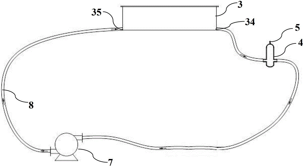
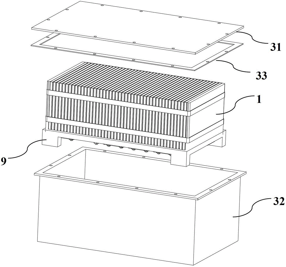
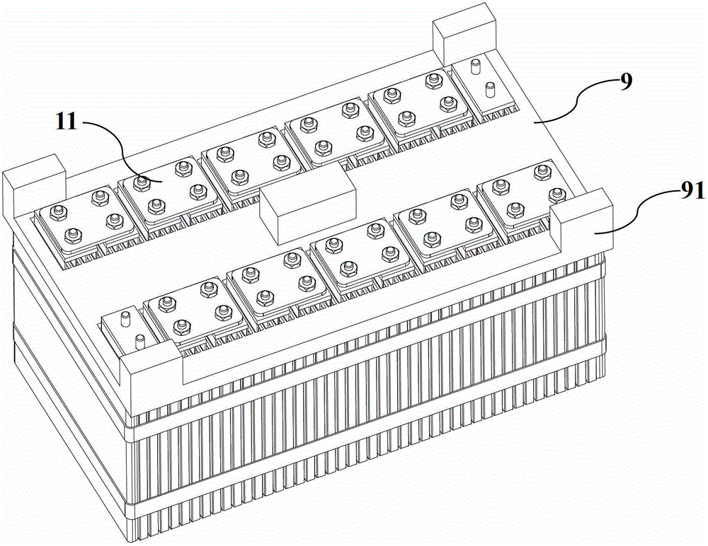
[0026] Such as Figure 1-Figure 5 As shown, the battery box 3 is composed of a box body 32 and a cover plate 31, and a sealing rubber pad 33 is used between the box body 32 and the cover plate 31 to seal the gap between the box body 32 and the cover plate 31, which can effectively seal the box body. Parts in 32 are isolated from air. A sheet battery is placed in the box 32, and several sheet batteries are stacked together to form a battery cell 1, and a spacer 6 is clamped between every two adjacent battery cells 1. In this solution, the spacer 6 Use a woven net, which is a plastic woven net whose warp and latitude lines are not on the same plane as the isolation component 6, which can well separate the battery cells 1, and can accelerate the circulation of the sealing solution 2, making the electrolyte more stable. It is easy...


PUM


Abstract

A battery pack system comprises a plurality of batteries, confining liquid, and a battery box containing the confining liquid; wherein the batteries are soaked in the confining liquid, the battery box is composed of a box body and a cover plate, the box body is provided with a confining liquid outlet and a confining liquid inlet, the outlet is connected to the inlet through a circulating pump and a buffer tank so as to form a circulating path, and a detection part is arranged in the buffer tank. When leakage happens in the batter pack, the electrolyte will flow in the confining liquid, then the confining liquid containing electrolyte goes through the buffer tank, electrolyte in the confining liquid is detected by the detection part in the buffer tank, and the detection part gives off a feedback signal. In this battery pack system, the leaked electrolyte is confined in the fire retardant confining liquid to prevent the electrolyte from contacting the air so as to prevent fire; the rupture of batteries can be detected immediately, and an alarm is given off at the same time, and thus the safety of battery box is improved.

Description

technical field [0001] The invention relates to a battery pack system, in particular to a battery pack system capable of detecting battery leakage. Background technique [0002] At present, battery-powered electric vehicles and electric buses are gradually replacing traditional cars and buses. The battery cell is the main energy storage device on the electric vehicle, and the battery box, as a device for loading the battery cell, is a key component of the electric vehicle, which directly affects the performance of the battery cell and thus affects the performance of the electric vehicle. Due to its excellent power output characteristics and long life, lithium-ion power batteries are currently widely used in electric vehicles. [0003] As the main energy storage device of electric vehicles, the battery cell is generally formed by connecting multiple batteries in series and parallel. During the charging process of the lithium-ion battery, the aprotic solvent in the electrolyt...

Claims


Application Information

Patent Timeline
Patent Type & Authority Applications(China)
IPC IPC(8): H01M10/48H01M10/613H01M10/625H01M2/10H01M50/202H01M50/244
CPCH01M10/4228H01M10/48H01M50/20Y02E60/10
Inventor 杨从明
Owner MICROVAST POWER SYST CO LTD
Learn More