
Environment-friendly device

A technology of environmental protection equipment and bottom plate, applied in metal processing equipment, grinding/polishing equipment, cleaning hollow objects, etc., can solve the problems of low labor intensity, low work efficiency, and high labor intensity of buried garbage compression boxes

Inactive Publication Date: 2018-08-10
江雪萍
View PDF10 Cites 5 Cited by
  • Summary
  • Abstract
  • Description
  • Claims
  • Application Information

AI Technical Summary

Problems solved by technology

[0003] In order to solve the above problems, the present invention provides a kind of environmental protection equipment, which can solve the need to manually repair the inner wall of the damaged garbage compression box in the maintenance and repair process of the inner wall of the existing urban underground garbage compression box, and manually repair the garbage. The compression box is inspected and maintained, and the rust on the garbage compression box is manually repaired. It is necessary to manually remove the accumulated dirt on the inner wall of the compression box with the help of tools, and it is necessary to manually use grinding tools to polish the rusted part of the inner wall of the compression box. It is time-consuming and laborious to eradicate the accumulated dirt. The noise generated by manual operation in a small space with the help of grinding tools seriously damages hearing. Manual work in the compression box for a long time, the pungent smell in the garbage compression seriously affects the health of the staff. Manual maintenance and repair The buried garbage compression box has problems such as high labor intensity and low work efficiency. It can realize the function of intelligent mechanical repair of the inner wall of the buried garbage compression box, without manual operation, without harming human health, and has the advantages of short time consumption and labor intensity. Small size and high work efficiency

Method used


Image

  • Environment-friendly device
  • Environment-friendly device
  • Environment-friendly device

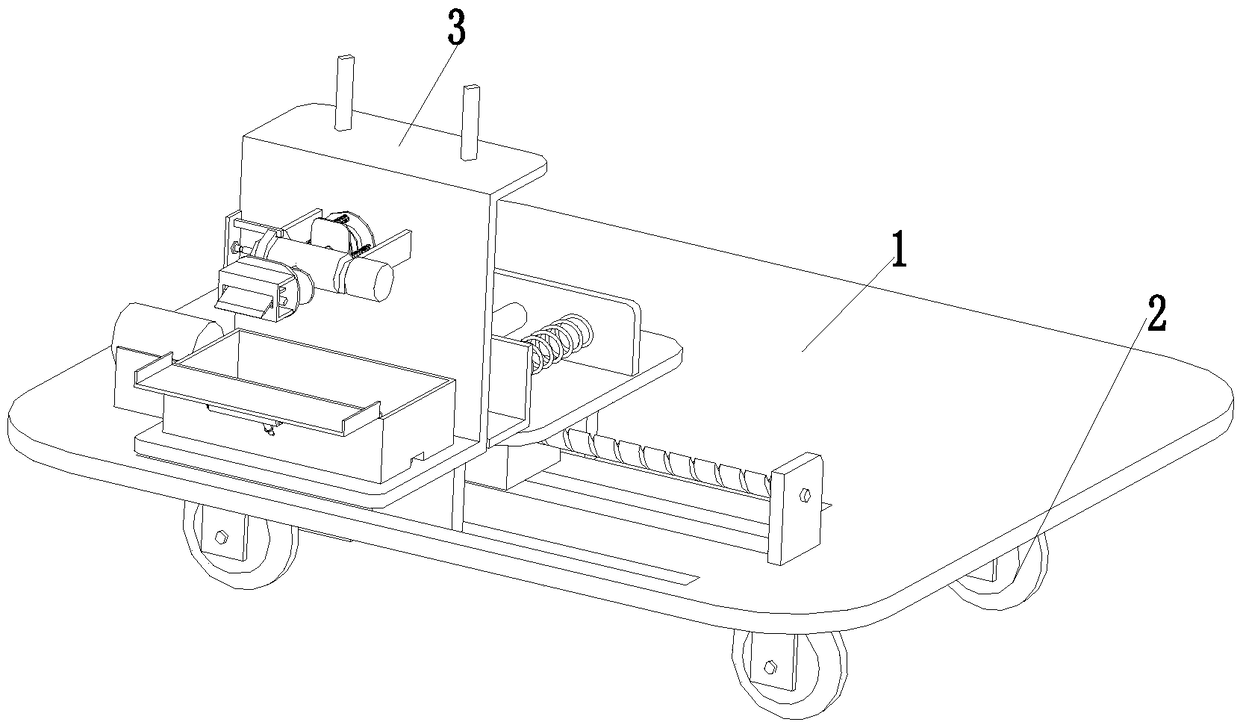
Examples


Embodiment Construction

[0023] In order to make it easy to understand the technical means, creation features, achieved goals and effects of the present invention, the present invention will be further described below with reference to the specific figures.

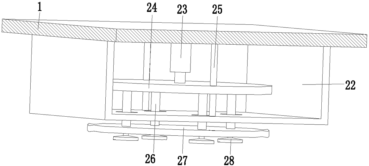
[0024] like Figure 1 to Figure 6 As shown, an environmental protection device includes a base plate 1, a travel limit device 2 is installed on the lower end of the base plate 1, a rust removal device 3 is installed on the front side of the upper end of the base plate 1, and a slag treatment device 4 is installed on the rear side of the upper end of the base plate 1 , the travel limiting device 2 can drive the present invention to move in the specified working area, and at the same time, it can be limited and fixed in the specified working position, and the rust removal device 3 can perform rust removal operations on the position where the inner wall of the compression box needs to be repaired , The slag treatment device 4 can clean and collect t...


PUM


Abstract

The invention discloses an environment-friendly device. The environment-friendly device comprises a bottom plate, traveling limiting devices are installed at the lower end of the bottom plate, and a rust removal device is installed on the front side of the upper end of the bottom plate; each traveling limiting device comprises a moving mechanism installed at the lower end of the bottom plate; anda limiting fixing frame is installed at the middle of the lower end of the bottom plate and is of a U-shaped structure, and limiting moving holes are uniformly formed in the lower end of the limitingfixing frame. According to the environment-friendly device, the problems that in an existing urban buried type garbage compression box inner wall maintenance and repair process, a damaged garbage compression box inner wall needs to be repaired manually, a garbage compression box needs to be checked and maintained manually, the rust on the garbage compression box needs to be repaired manually, dirty slag accumulated on the compression box inner wall needs to be removed manually by means of a tool, and rusted parts on the compression box inner wall need to be ground manually by means of a grinding tool are solved.

Description

technical field [0001] The invention relates to the technical field of environmental protection machine maintenance and repair equipment, in particular to an environmental protection equipment. Background technique [0002] With the continuous improvement of people's living standards, the requirements for environmental conditions are also increasing. The traditional garbage stations in urban and rural areas can no longer meet people's requirements for new concepts such as high efficiency, environmental protection, energy saving and low consumption. Therefore, the promotion of compressed garbage stations is inevitable. Must do. The compressed garbage transfer station leads the development of the garbage transfer station industry with its advantages of small footprint, good concealment and reasonable spatial structure. The traditional garbage transfer station not only pollutes the environment, but also has serious odor and odor, and breeds a large number of mosquitoes and fli...

Claims


Application Information

Patent Timeline
Patent Type & Authority Applications(China)
IPC IPC(8): B24B27/033B24B41/02B24B41/00B24B47/00B08B9/087B08B13/00
CPCB24B27/033B08B9/083B08B9/087B08B13/00B24B27/0007B24B41/007B24B41/02B24B47/00
Inventor 不公告发明人
Owner 江雪萍
Learn More