Perforating device for power installation

A drilling device and a technology for installation, which are applied in the direction of supporting devices, drilling with mechanical conveying devices, drilling equipment and methods, etc., can solve the problems that the power source is greatly affected, not enough for drilling, and the motor burns out. , to achieve the effect of reducing labor intensity, improving utilization rate and strong practicability

Active Publication Date: 2018-08-10
威海成达电力设备安装工程有限公司
View PDF3 Cites 2 Cited by
  • Summary
  • Abstract
  • Description
  • Claims
  • Application Information

AI Technical Summary

Problems solved by technology

[0002] At present, when installing electric cement poles, it is necessary to bury the bottom of the cement poles in the ground, so a puncher has to be used, and the rotating spindle driven by the motor of a general puncher is fixedly connected to the motor. , once the rotating blade encounters a hard geological situation, it is likely to cause the motor to burn out, and the above-mentioned device needs to be used under the premise of sufficient power. For some remote areas, there is no power, and you need to bring your own battery. However, the power is far from enough for punching holes, so its use has relatively large limitations and is greatly affected by the power source.

Method used


Image

  • Perforating device for power installation
  • Perforating device for power installation
  • Perforating device for power installation

Examples


Embodiment Construction

[0020] The following will clearly and completely describe the technical solutions in the embodiments of the present invention with reference to the accompanying drawings in the embodiments of the present invention. Obviously, the described embodiments are only some, not all, embodiments of the present invention. Based on the embodiments of the present invention, all other embodiments obtained by persons of ordinary skill in the art without making creative efforts belong to the protection scope of the present invention.

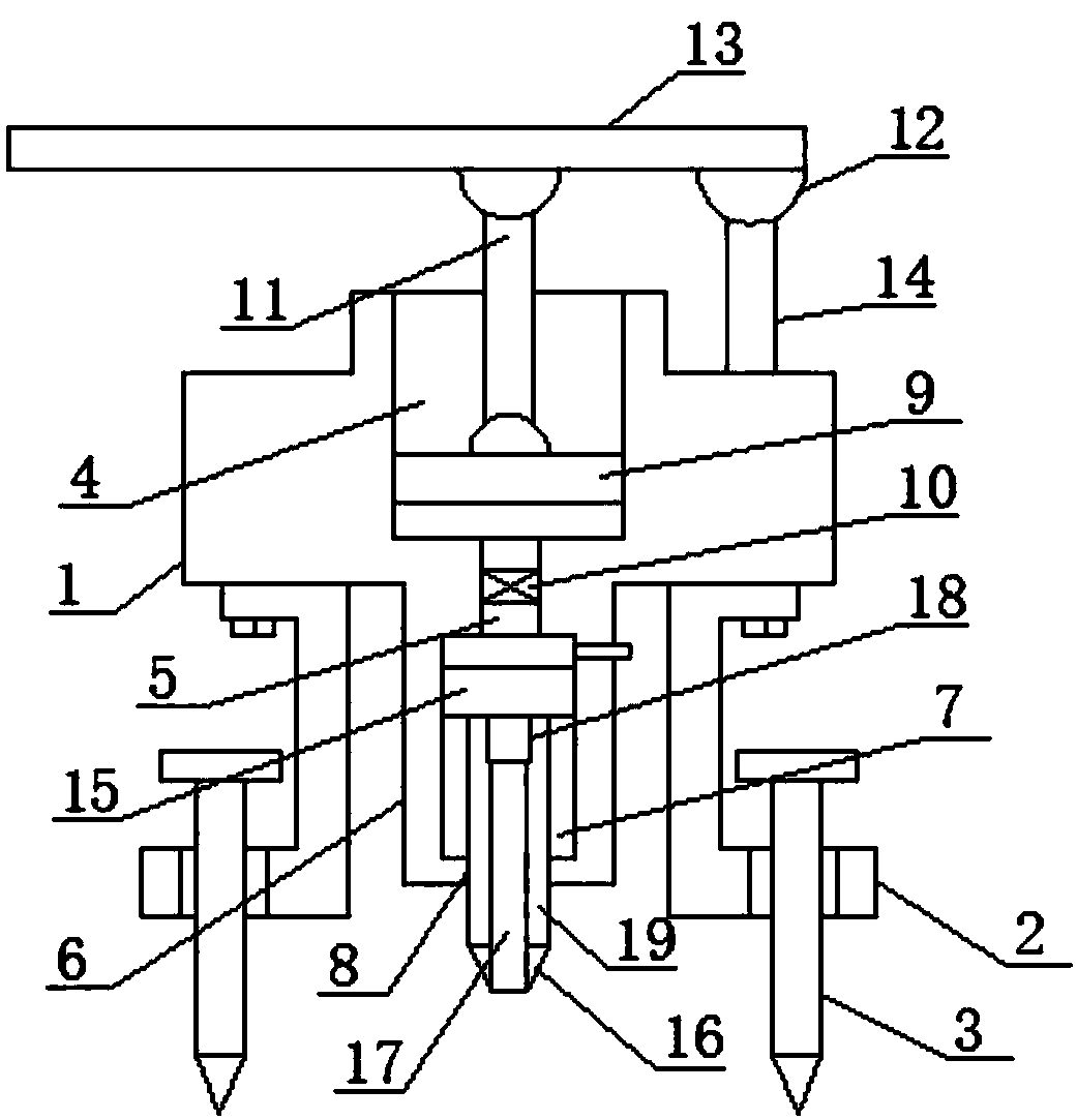
[0021] see figure 1, an embodiment provided by the present invention: comprising a main hollow shell 1, a columnar cylinder 19 and a columnar cylinder sludge discharge mechanism, the bottom side of the main hollow shell 1 is installed with a support plate 2 through bolts, The inside of the bottom of the support plate 2 is inserted with a limit steel nail 3, the center of the upper surface of the main hollow shell 1 is provided with a secondary hollow structure...


PUM


Abstract

The invention discloses a perforating device for power installation. The device comprises a main hollow shell body, a columnar cylinder and a columnar cylinder sludge exporting mechanism, wherein theside face of the bottom of the main hollow shell body is provided with a supporting plate through a bolt. According to the perforating device for power installation, other energy sources are not needed as power sources, the device utilizes a lever principle to achieve the injection of air pressure, the device is characterized in that the labor intensity of force application each time is reduced, the operation is convenient and simple, and the practicability is strong; in addition, the device is provided with the columnar cylinder sludge exporting mechanism, and the columnar cylinder sludge exporting mechanism can directly clear away the sludge in the columnar cylinder, thereby continuing working; the device is provided with an air unidirectional compression mechanism, on the premise of driving, the air unidirectional compression mechanism can utilize the available air to achieve aerodynamic compression, thereby performing driving; the device is also provided with a driven movable buttjoint mechanism, the driven movable butt joint mechanism is in threaded connection with the columnar cylinder used for working, thereby driving the columnar cylinder, the assembly and disassembly of the columnar cylinder can also be achieved, and the utilization rate is improved.

Description

technical field [0001] The invention relates to the technical field of electric power construction, in particular to a punching device for electric power installation. Background technique [0002] At present, when installing electric cement poles, it is necessary to bury the bottom of the cement poles in the ground, so a puncher has to be used, and the rotating spindle driven by the motor of a general puncher is fixedly connected to the motor. , once the rotating blade encounters a hard geological situation, it is likely to cause the motor to burn out, and the above-mentioned device needs to be used under the premise of sufficient power. For some remote areas, there is no power, and you need to bring your own battery. However, the power is far from enough for punching holes, so it has relatively large limitations in use and is greatly affected by the power source. Contents of the invention [0003] The object of the present invention is to provide a punching device for e...

Claims


Application Information

Patent Timeline
Patent Type & Authority Applications(China)
IPC IPC(8): E21B7/00E21B11/00E21B15/00
CPCE21B7/005E21B11/005E21B15/006
Inventor 陈强发
Owner 威海成达电力设备安装工程有限公司
Why Eureka
Try Eureka