Control mechanism of exhaust brake valve

A technology of exhaust brake valve and operating mechanism, which is applied in the direction of machine/engine, mechanical equipment, engine control, etc., and can solve the problems of partial wear of piston push rod, easy partial wear and card issuance of piston push rod, and easy failure of control mechanism, etc. , to achieve the effect of reducing connection, improving the condition of partial wear and card issuance, and solving the effect of partial wear and card issuance

Active Publication Date: 2018-08-10
DONGFENG COMML VEHICLE CO LTD
View PDF9 Cites 0 Cited by
  • Summary
  • Abstract
  • Description
  • Claims
  • Application Information

AI Technical Summary

Problems solved by technology

[0005] The purpose of the present invention is to overcome the defects and problems in the prior art that the operating mechanism is easy to fail, the piston push rod is easy to be worn out and the card is issued, and to provide an exhaust that can effectively solve the problems of the control mechanism failure, the piston push rod and the issue of the card. Air brake valve operating mechanism

Method used


Image

  • Control mechanism of exhaust brake valve
  • Control mechanism of exhaust brake valve
  • Control mechanism of exhaust brake valve

Examples


Embodiment

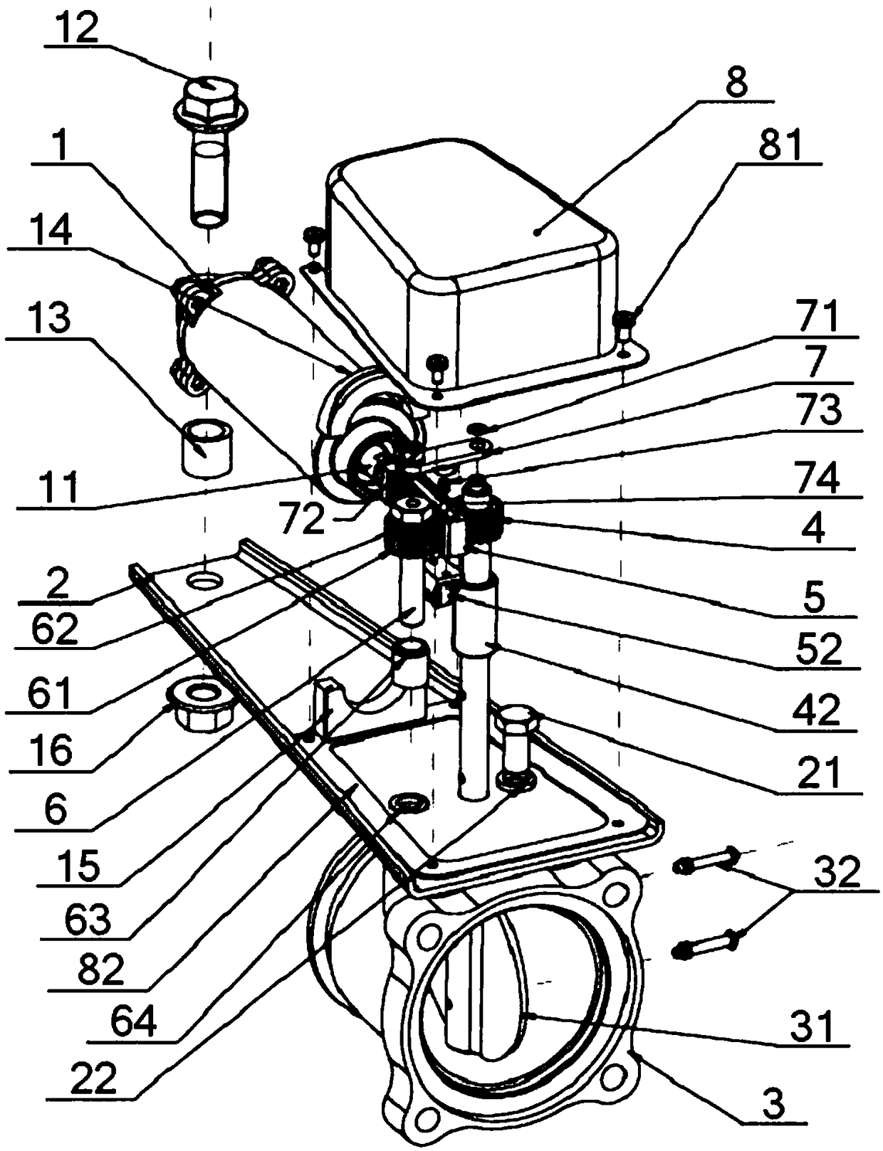
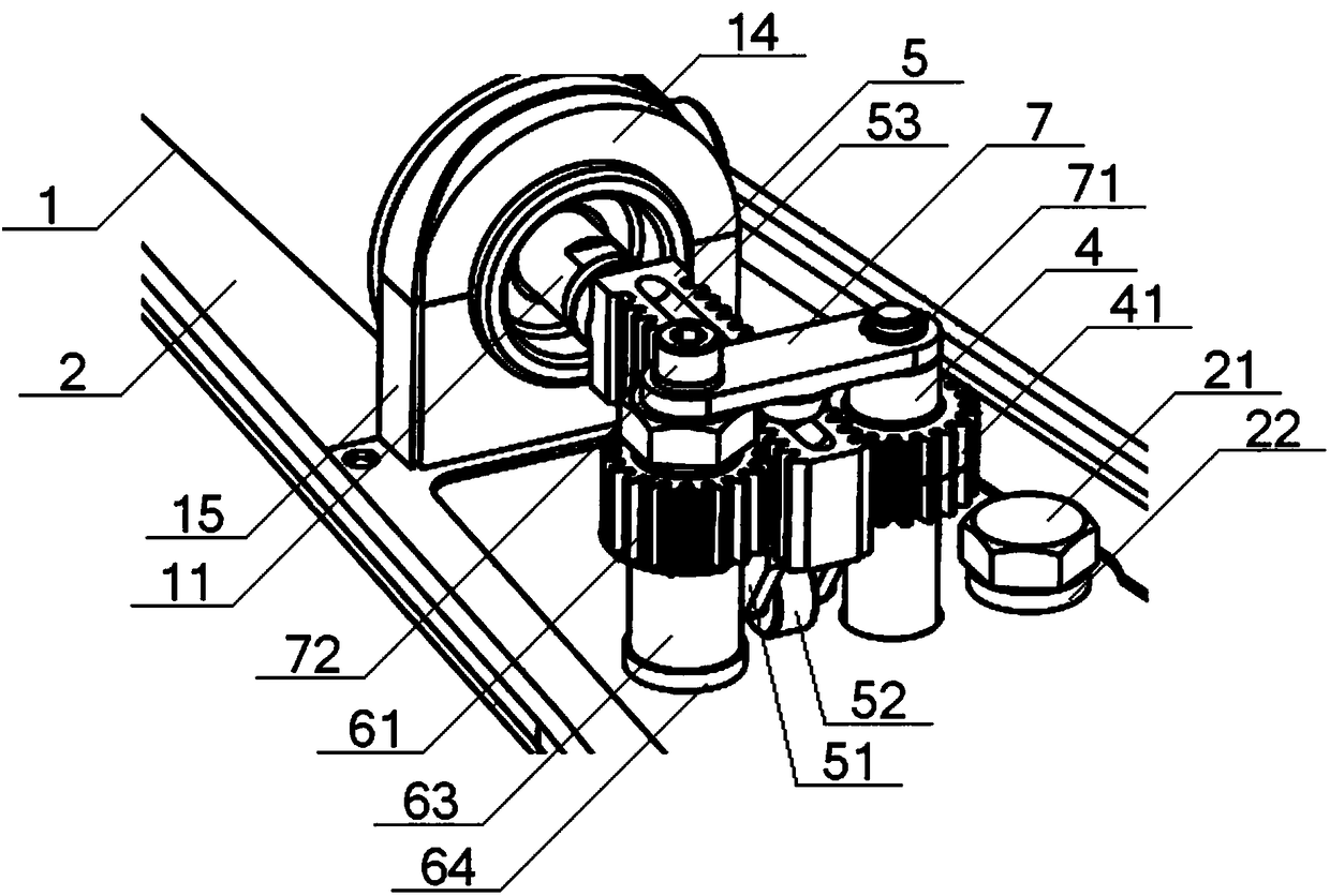
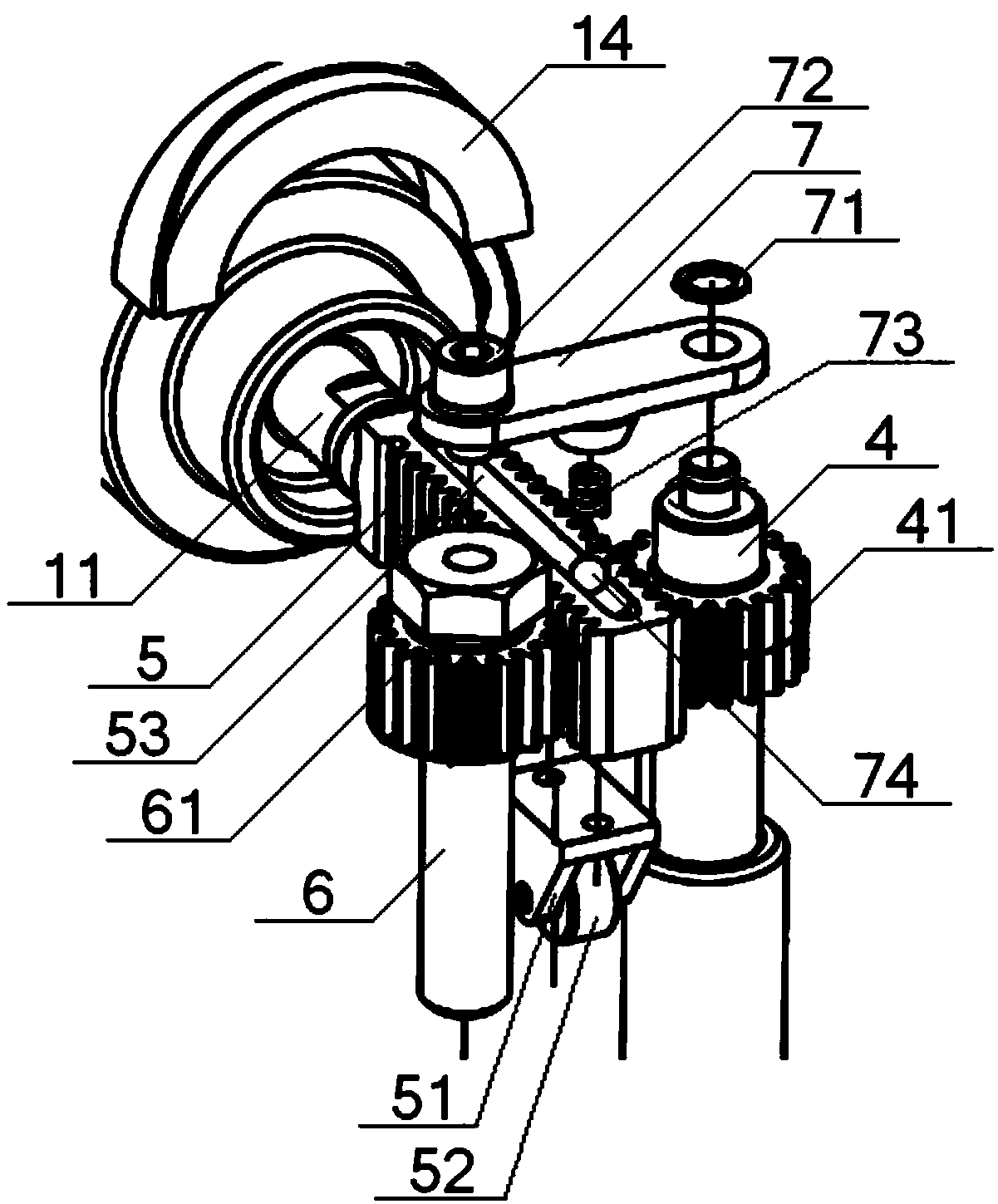
[0045] see Figure 1 to Figure 6 , an exhaust brake valve operating mechanism, including an operating cylinder 1, a support plate 2, a valve body 3, a rotating shaft 4, a rack 5, an idler shaft 6, and a cover 8, and the operating cylinder 1 is installed on the support plate 2 On the upper end face, the valve body 3 is installed on the lower end face of the support plate 2, and one end of the rotating shaft 4 on the same side as the operating cylinder 1 is provided with a gear 41, and the other end of the rotating shaft 4 passes through the supporting plate 2, valve The body 3 is connected with the valve plate 31 in the valve body 3, the idler shaft 6 and the rotating shaft 4 are parallel to each other, one end of the idler shaft 6 is connected with the support plate 2, and the other end of the idler shaft 6 is sleeved with an idler 61 , one end of the rack 5 is connected with the piston push rod 11 of the operating cylinder 1, the other end of the rack 5 is located between the...


PUM


Abstract

A control mechanism of an exhaust brake valve comprises a control cylinder, a supporting plate, a valve body, a rotary shaft, a rack, an idler shaft and a hood; one end of the rotary shaft is providedwith a gear in a sleeved mode, and the other end of the rotary shaft penetrates through the supporting plate and the valve body in sequence to be connected with a valve plate in the valve body; one end of the idler shaft is connected with the supporting plate, and an idler is arranged at the other end of the idler shaft; one end of the rack is connected with a piston push rod of the control cylinder, the other end of the rack is located between the rotary shaft and the idler shaft, and the rack is engaged with the gear and the idler; a roller support with a roller is installed on the lower end face of the rack; and a pressing plate is arranged above the rack, the end parts of the pressing plate are fixed to the rotary shaft and the idler shaft correspondingly, a spring and a ball are installed on the lower end face of the pressing plate, a groove is formed in the upper end face of the rack, and the ball is pressed in the groove through the spring. By means of the control mechanism ofthe exhaust brake valve, the problems that a control mechanism loses efficacy and a piston push rod is eccentrically worn and gets stuck can be effectively solved, and the control mechanism is long inservice life, high in reliability and good in smoothness.

Description

technical field [0001] The invention relates to an engine exhaust brake valve, in particular to an exhaust brake valve operating mechanism, which is mainly suitable for solving the problems of the failure of the operating mechanism and the eccentric wear and pinning of the piston push rod. Background technique [0002] The current exhaust brake valve mainly pushes the piston push rod to move by manipulating the compressed air in the cylinder, and then pushes a rocker arm fixedly connected with the valve plate rotating shaft to rotate, thereby realizing the closing of the brake valve plate. When the compressed air pressure is removed, the brake valve plate is reset under the action of the exhaust pressure of the engine, which in turn drives the rotation shaft of the valve plate, thereby pushing the rocker arm to rotate, and realizing the reset of the piston push rod; the tail of the control cylinder is fixed on the On the support plate of the steering cylinder, during the who...

Claims


Application Information

Patent Timeline
Patent Type & Authority Applications(China)
IPC IPC(8): F02D9/10
CPCF02D9/10F02D9/1065Y02T10/12
Inventor 范雨张芳吴囿霖
Owner DONGFENG COMML VEHICLE CO LTD
Why Eureka
Try Eureka