Stress optical cable underground laying and protection method used for transformer substation foundation displacement monitoring

A technology of displacement monitoring and underground laying, applied in the direction of optical device, optical fiber/cable installation, optical, etc., can solve problems such as soil erosion, ground cracking, affecting the safe and stable operation of the power grid, and achieve the effect of prolonging the service life

Active Publication Date: 2018-08-10
QINGYUAN POWER SUPPLY BUREAU OF GUANGDONG POWER GRID CO LTD
View PDF7 Cites 1 Cited by
  • Summary
  • Abstract
  • Description
  • Claims
  • Application Information

AI Technical Summary

Problems solved by technology

At the same time, these areas are rainy in summer, and the rainwater penetrates into the geological erosion of substations, leading to geological disasters such as soil erosion, cracking and collapse of the ground, which will also pose a potential threat to the operation of substations and affect the safe and stable operation of the power grid.

Method used


Image

  • Stress optical cable underground laying and protection method used for transformer substation foundation displacement monitoring
  • Stress optical cable underground laying and protection method used for transformer substation foundation displacement monitoring
  • Stress optical cable underground laying and protection method used for transformer substation foundation displacement monitoring

Examples


Embodiment 1

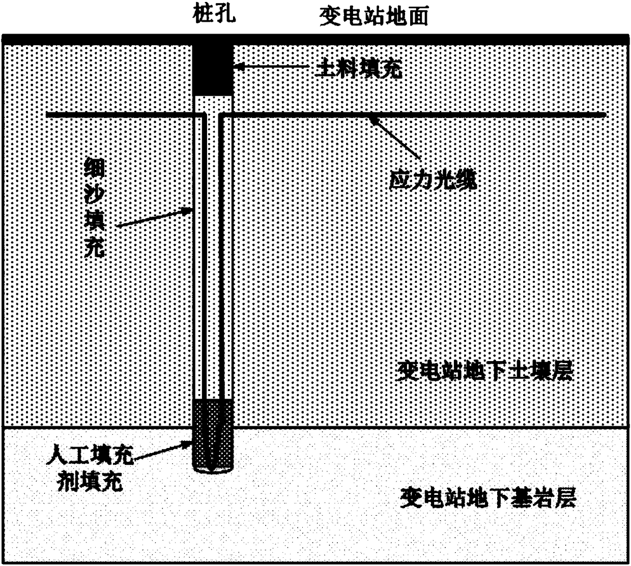
[0026] Such as figure 1 As shown, it is a schematic cross-sectional view of the method of underground laying of stress optical cables through pile holes perpendicular to the ground. figure 1 Among them, the pile hole is perpendicular to the ground, the depth of the pile hole passes through the soil layer of the foundation to the bedrock layer, and the depth of the optical cable into the ground also reaches the bedrock layer. The diameter of the pile hole meets the requirements of the bending curvature of the optical cable after entering the ground, which is equivalent to allowing the optical cable to enter the pile hole and then return to the ground after bending, that is, the diameter of the pile hole should be significantly larger than twice the diameter of the optical cable. When backfilling the pile hole after the optical cable is put into the ground, first use a certain amount of artificial filler to backfill the pile hole until the artificial filler completely covers the...


PUM


Abstract

The invention provides a stress optical cable underground laying and protection method used for transformer substation foundation displacement monitoring. According to the method, one end of the stress optical cable is buried in the deep soil and the bedrock of the transformer substation through a pile hole so as to monitor the specific area of foundation settlement; then the rest part of the stress optical cable is buried in the soft soil layer of the superficial layer of the surface so as to monitor the soil tangential deformation and the water and soil erosion, wherein the stress optical cable is buried in the ground through the pile hole, then the pile hole is backfilled by using the artificial filler until the artificial filler completely covers the bending part of the optical cable under the condition of ensuring that the optical fiber signal in the optical cable is normal, then the pile hole is filled by using the fine sand and finally the pile hole is backfilled by using the soil material; meanwhile, the soil of the superficial layer is excavated by using the U-shaped groove when the stress optical cable is buried in the soft soil layer of the superficial layer of the surface, the fine sand is laid on the groove bottom, then the stress optical cable is laid, then the artificial filler is laid to cover the stress optical cable and finally the stress optical cable is buried by using the soil.

Description

technical field [0001] The invention relates to the technical field of disaster prevention and mitigation in electric power systems, and more specifically, relates to an underground laying and protection method for stressed optical cables used for substation foundation displacement monitoring. Background technique [0002] Power substation is an important hub of power energy transmission and conversion, and also a key infrastructure facility of the national energy network. In the past, substations were usually located in areas with solid foundations and high terrain. With the development of economy and society, land resources are decreasing day by day, more and more plains, tidal flats, and low-lying areas are being developed and utilized, and substations in cities and adjacent cities have to be built in areas that were not suitable for building stations. What followed was that the problem of substation foundation settlement became increasingly prominent, especially in the ...

Claims


Application Information

Patent Timeline
Patent Type & Authority Applications(China)
IPC IPC(8): G02B6/50G01B11/02
CPCG02B6/504G01B11/02
Inventor 王文博胡金磊王伟罗建军林孝斌温爱辉
Owner QINGYUAN POWER SUPPLY BUREAU OF GUANGDONG POWER GRID CO LTD
Why Eureka
Try Eureka