
A three-dimensional simulation experimental device and experimental method of a reactor cavity water injection system

A simulated experimental device and reactor cavity water injection technology, applied in the field of reactors, can solve the problems of low cooling capacity of water injection, low safety margin of critical heat flux on the outer wall of the pressure vessel, etc., achieve good water injection flow rate and water injection supercooling degree, and optimize the insulation layer Simulate the body structure and improve the effect of safety margin

Active Publication Date: 2019-11-05
LINGDONG NUCLEAR POWER +4
View PDF8 Cites 1 Cited by
  • Summary
  • Abstract
  • Description
  • Claims
  • Application Information

AI Technical Summary

Problems solved by technology

[0003] The object of the present invention is to provide a three-dimensional simulation experiment device for the reactor cavity water injection system, which aims to solve the problems of the existing reactor cavity water injection system with low water injection cooling capacity and the critical heat flux safety margin of the outer wall of the pressure vessel.

Method used


Image

  • A three-dimensional simulation experimental device and experimental method of a reactor cavity water injection system
  • A three-dimensional simulation experimental device and experimental method of a reactor cavity water injection system
  • A three-dimensional simulation experimental device and experimental method of a reactor cavity water injection system

Examples


Embodiment Construction

[0024] In order to make the technical problems, technical solutions and beneficial effects to be solved by the present invention clearer, the present invention will be further described in detail below in conjunction with the accompanying drawings and embodiments. It should be understood that the specific embodiments described here are only used to explain the present invention, not to limit the present invention.

[0025] It should be noted that when an element is referred to as being “fixed” or “disposed on” another element, it may be directly on the other element or be indirectly on the other element. When an element is referred to as being "connected to" another element, it can be directly connected to the other element or indirectly connected to the other element.

[0026] It is to be understood that the terms "length", "width", "top", "bottom", "front", "rear", "left", "right", "vertical", "horizontal", "top" , "bottom", "inner", "outer" and other indicated orientations...


PUM


Abstract

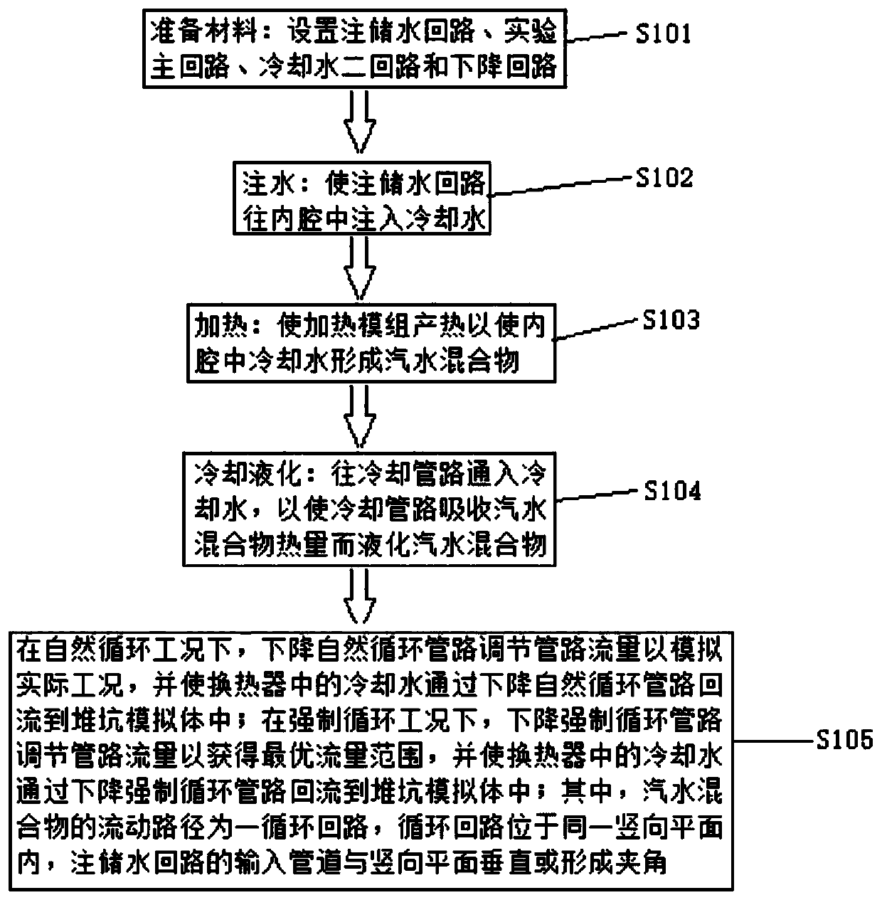
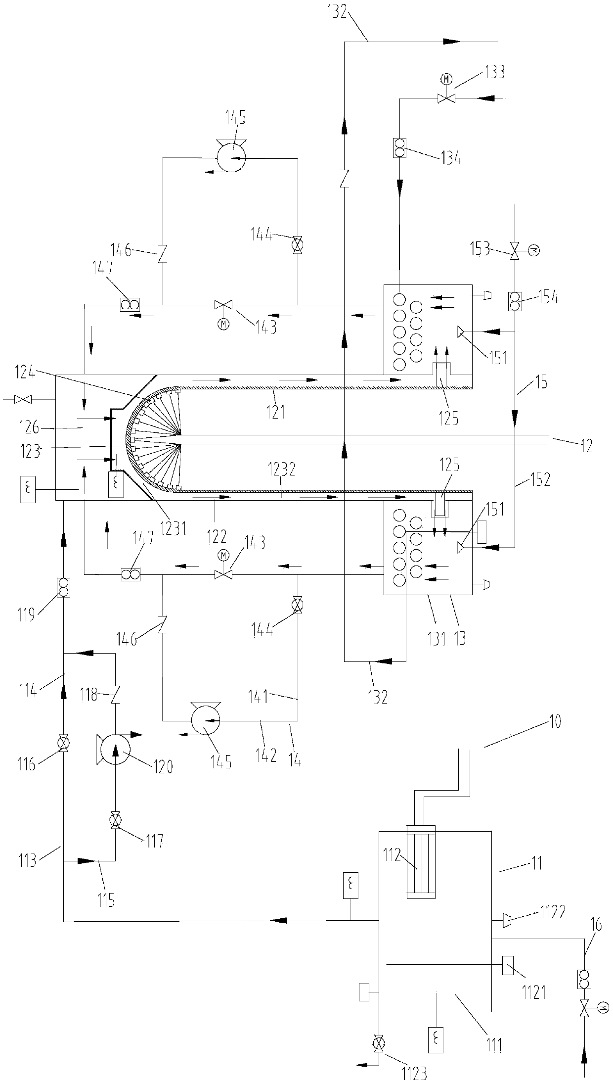
The invention provides a reactor external reactor vessel cooling (ERVC) system three-dimensional simulation experiment apparatus and a reactor external reactor vessel cooling (ERVC) system three-dimensional simulation experiment method. The experiment apparatus comprises an injection water storage circuit, an experiment main circuit, a cooling water secondary circuit and a descending circuit, wherein the experiment main circuit comprises a reactor pit simulation body, a pressure container simulation body, a thermal insulation layer simulation body, a cavity body and a heating module, the cooling water secondary circuit comprises a heat exchanger and a cooling pipeline, the descending circuit comprises a natural descending circulation pipeline and a forced descending circulation pipeline, and the vertical plane of a steam-water mixture flowing path is perpendicular to the input pipeline of the injection water storage circuit or an included angle is formed between the vertical plane of asteam-water mixture flowing path and the input pipeline of the injection water storage circuit. With the experiment apparatus and the experiment method of the present invention, the ERVC experimentsunder the natural circulation condition and the forced circulation condition can be achieved by simulating the ERVC process of the actual external reactor vessel, and the water injection flow and thewater injection undercooling can be well adjusted by combining the three-dimensional water supply flow path, such that the ERVC capacity of the reactor and the safety margin of the critical heat fluxdensity on the outer wall of the pressure vessel can be improved.

Description

technical field [0001] The invention belongs to the technical field of reactors, and more specifically relates to a three-dimensional simulation experiment device and an experiment method for a reactor cavity water injection system. Background technique [0002] In the field of existing nuclear power plant reactor cavity water injection technology, the design and construction of the reactor cavity water injection system is usually obtained through one-dimensional and two-dimensional experiments and theoretical design, which is quite different from the actual engineering application and lacks a better solution. Therefore, the existing reactor cavity water injection system still has such problems: the water injection cooling capacity of the reactor cavity and the critical heat flux safety margin of the outer wall of the pressure vessel are both low, and the three-dimensional flow field The effect on the cooling capacity of cooling water has not been proved by effective experim...

Claims


Application Information

Patent Timeline
Patent Type & Authority Patents(China)
IPC IPC(8): G21C15/243G21C15/18
CPCG21C15/18G21C15/243Y02E30/30
Inventor 阳立梁峻铭陈军郑超雄张会勇张雷徐俊英
Owner LINGDONG NUCLEAR POWER
Learn More