
Array substrate and display panel

A technology for array substrates and display panels, applied in optics, instruments, electrical components, etc., can solve problems such as abnormal power consumption, short circuit of conductive particles, and incomplete etching of metal layers, and achieve the effect of reducing the possibility of short circuit and preventing short circuit

Inactive Publication Date: 2018-08-10
WUHAN CHINA STAR OPTOELECTRONICS TECH CO LTD
View PDF7 Cites 17 Cited by
  • Summary
  • Abstract
  • Description
  • Claims
  • Application Information

AI Technical Summary

Problems solved by technology

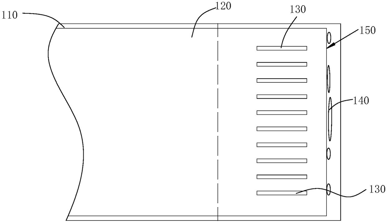
[0003] However, when forming the pixel electrodes, it is necessary to first deposit a whole layer of metal layer on the flat layer 120 and other areas of the array substrate. The material of the metal layer is, for example, ITO. There is a relatively large height difference at the first side boundary 150 of the layer 120 close to the connection terminal 130, and the etching of the metal layer on the outside of the flat layer 120 close to the first side boundary 150 of the connection terminal 130 may not be complete, and there may be residual metal 140, As a result, when the signal terminal and the connection terminal 130 are electrically connected through the conductive glue, the residual metal 140 will cause a short circuit of the conductive particles in the conductive glue, or cause a short circuit between two adjacent signal terminals, resulting in a large current abnormality, causing the display screen to display There is an exception, and the power consumption is seriously abnormal when the screen is off

Method used


Image

  • Array substrate and display panel
  • Array substrate and display panel
  • Array substrate and display panel

Examples


Embodiment Construction

[0036] The following will clearly and completely describe the technical solutions in the embodiments of the present invention with reference to the accompanying drawings in the embodiments of the present invention. Obviously, the described embodiments are only some, not all, embodiments of the present invention. Based on the embodiments of the present invention, all other embodiments obtained by persons of ordinary skill in the art without creative efforts fall within the protection scope of the present invention.

[0037] The terms "comprising" and "having" and any variations thereof appearing in the specification, claims and drawings of this application are intended to cover non-exclusive inclusion. For example, a process, method, system, product or device comprising a series of steps or units is not limited to the listed steps or units, but optionally also includes unlisted steps or units, or optionally further includes For other steps or units inherent in these processes, ...


PUM


Abstract

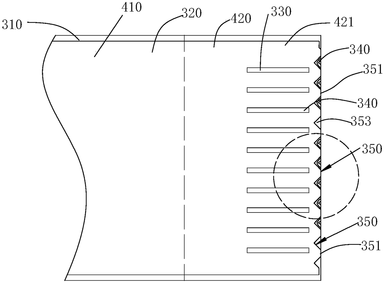
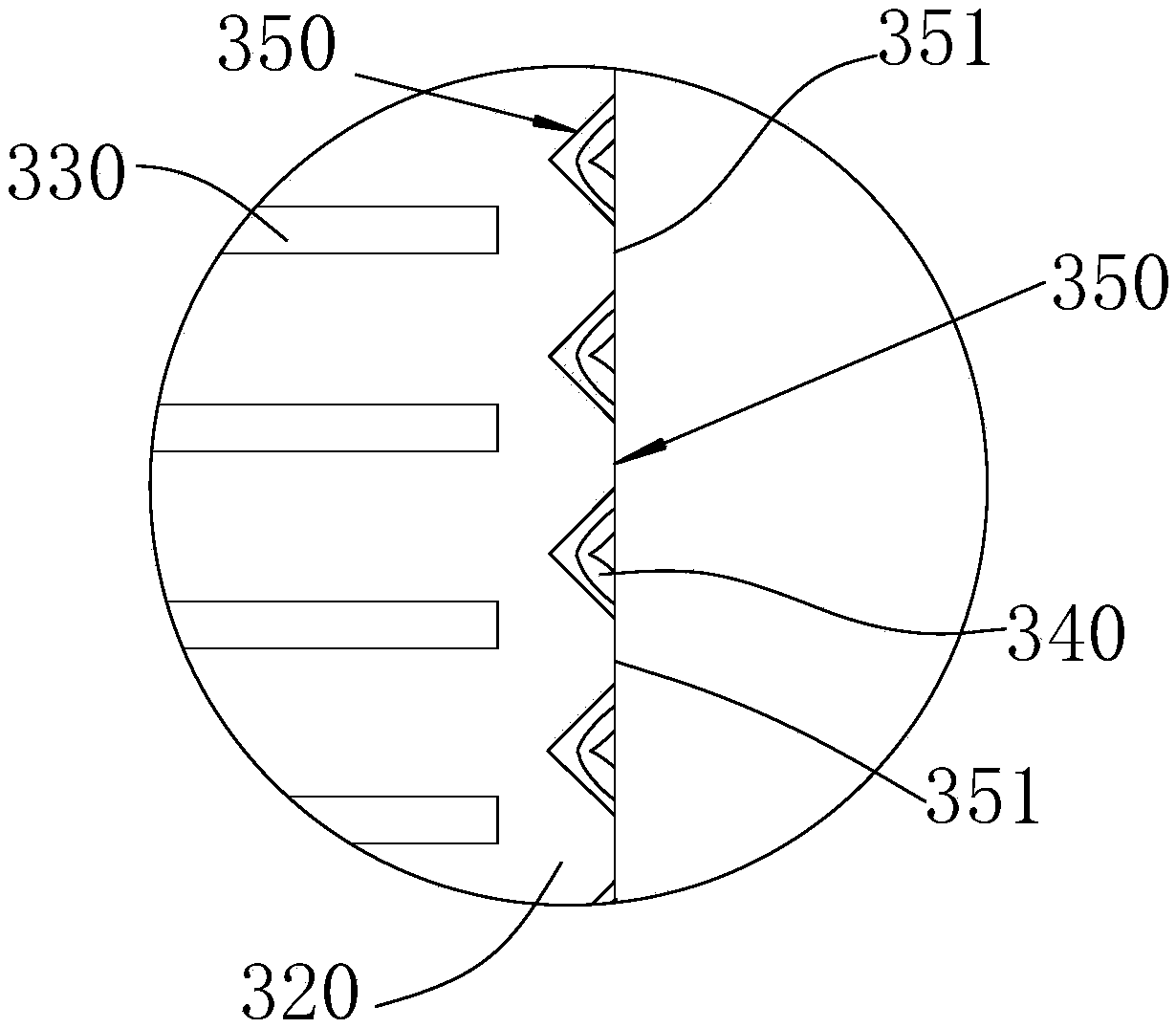
The invention discloses an array substrate. The array substrate comprises a substrate body, connection terminals, a flat layer and pixel electrodes; the connecting terminals are positioned on the substrate body, arranged close to the boundary of the substrate body, and electrically connected with a flexible circuit board; the flat layer is positioned on the substrate body, and a first boundary ofthe flat layer is positioned outside the connecting terminals; the pixel electrodes are positioned on the flat layer; and at least part of the first boundary of the flat layer are recessed inwardly toform recess parts, and a planar part is formed between two adjacent recess parts by cutting. The invention discloses a display panel. Thus, short circuit caused by residual metal is reduced.

Description

technical field [0001] The present invention relates to the field of display technology, in particular to an array substrate and a display panel. Background technique [0002] A display panel generally includes an array substrate, a color filter substrate and a flexible circuit board, and the array substrate and the color filter substrate are assembled together. See figure 1 , the array substrate includes a base substrate 110, a plurality of connection terminals 130, a flat layer 120, a pixel electrode (not shown in the figure), etc., and a plurality of the connection terminals 130 and the flat layer 120 are formed on the base substrate 110, The pixel electrodes are formed on the flat layer 120, and the plurality of connection terminals 130 are electrically connected to the flexible circuit board through conductive glue. Specifically, the flexible circuit board is provided with a plurality of signal terminals, and the signal terminals are respectively electrically connecte...

Claims


Application Information

Patent Timeline
Patent Type & Authority Applications(China)
IPC IPC(8): H01L27/12G02F1/1362
CPCG02F1/1362H01L27/1218H01L27/1244
Inventor 安喜锋
Owner WUHAN CHINA STAR OPTOELECTRONICS TECH CO LTD
Learn More