Whole body scanning device and scanning method based on 3D imaging technology
A whole-body scanning and scanning method technology, applied in the field of whole-body scanning devices, can solve the problems of insufficient clarity, distortion, and inconvenient acquisition of images, and achieve the effect of clear images and easy post-processing
- Summary
- Abstract
- Description
- Claims
- Application Information
AI Technical Summary
Problems solved by technology
Method used
Image
Examples
Embodiment 1
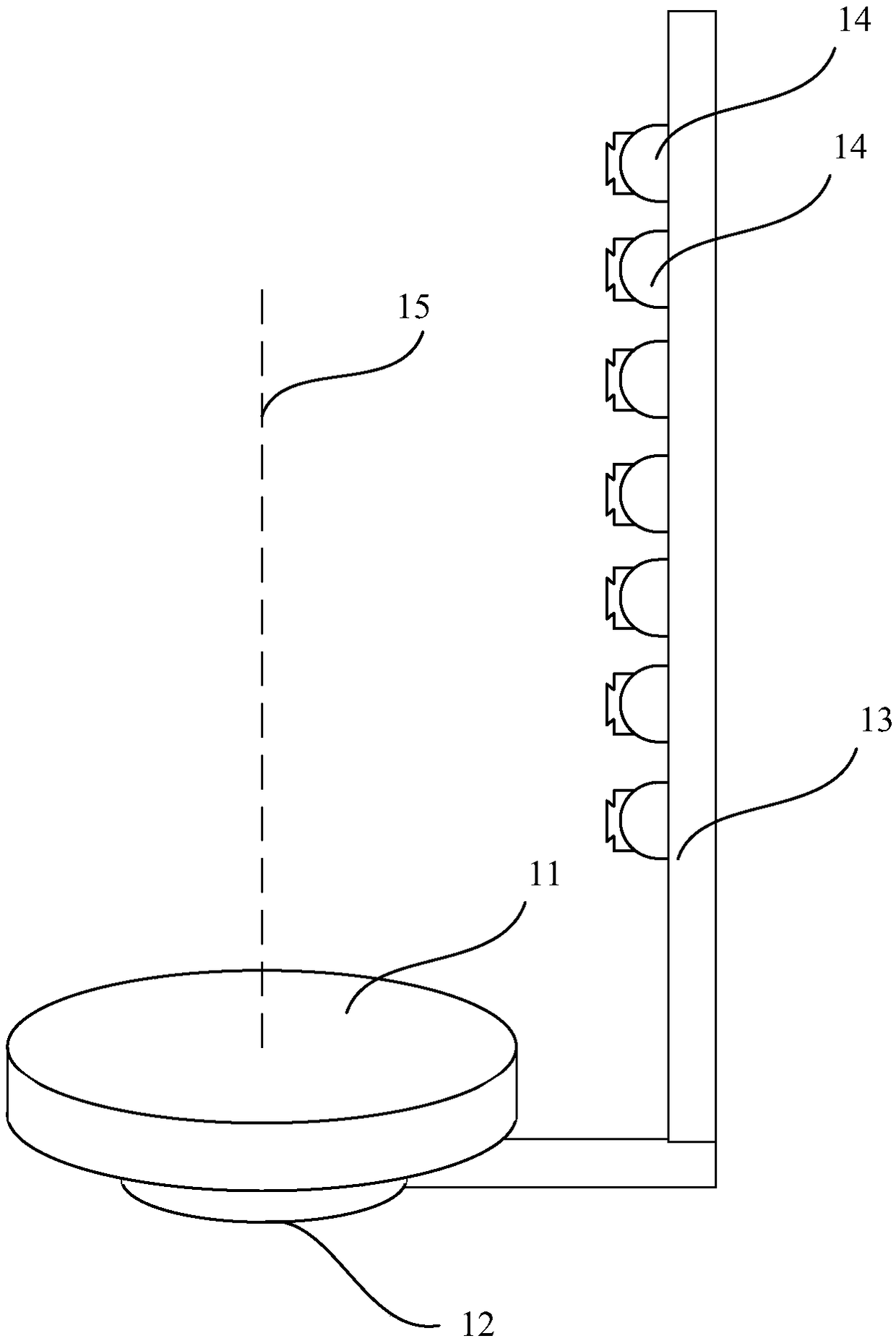
[0046] See figure 1 This embodiment provides a whole body scanning device based on 3D imaging technology. The whole body scanning device includes a tray 11, a supporting portion 12, a rotating device, a supporting rod 13, seven 3D cameras 14 and a processing end.
[0047] In this embodiment, the processing end is a computer, and the processing end may also be a cloud server. The cloud server is used to perform data operations by transmitting data to the cloud server.
[0048] The tray is installed on the supporting part by the rotating device, and the tray is horizontally rotated around the axis of the rotating device on the supporting part by the rotating device.
[0049] The support rod is perpendicular to the plane where the tray is located.
[0050] The 7 3D cameras are longitudinally arranged side by side on the support rod.
[0051] The shooting direction of the 3D camera is from the 3D camera to a point on the axis 15.
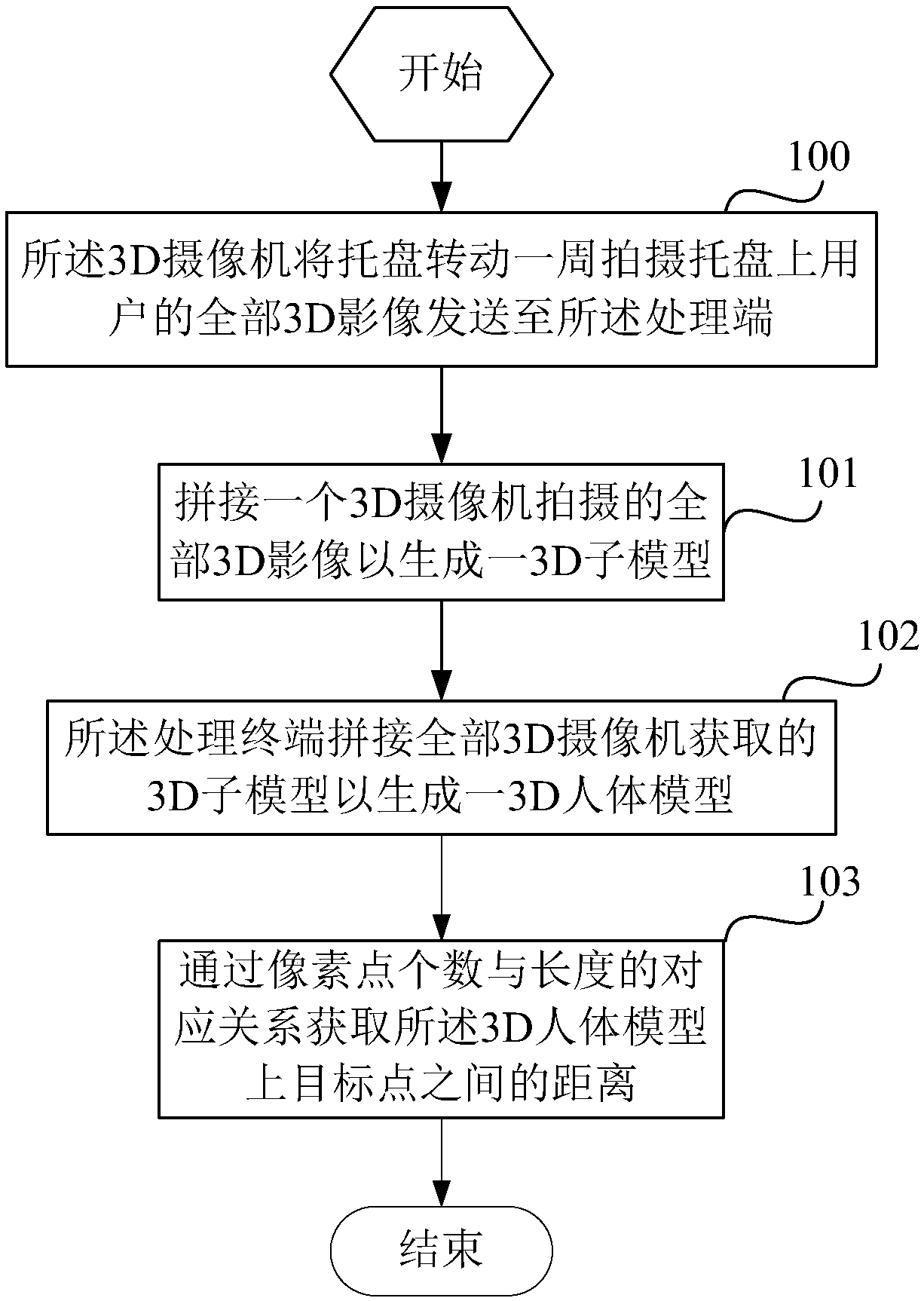
[0052] The 3D camera is used to send all the 3D images of th...
Embodiment 2
[0072] This embodiment is basically the same as Embodiment 1, and the only difference is:
[0073] For a target 3D image obtained by a 3D camera, the processing end is used to select a feature point in the target 3D image, and obtain the distance from the feature point to the axis and the target included angle, and then pass the angle of the tray rotation, The distance between the feature point and the axis and the target included angle determine the location of the feature point in the next 3D image of the target 3D image, and combine the target 3D image with the next 3D image of the target 3D image. The images are stitched at the feature points, wherein the target included angle is the angle between the line from the feature point to the axis projection point and the 3D camera and the plane where the axis is located;
[0074] For two adjacent 3D sub-models, the processing end is also used to capture images of the 3D sub-models in the longitudinal direction, and stitch the two 3D ...
Embodiment 3
[0080] This embodiment is basically the same as Embodiment 1, and the only difference is:
[0081] The support rod includes a first section and a second section, the second section being perpendicular to the plane where the tray is located; the value interval of the angle formed by the first section and the second section is [90, 180] degrees, The first section is provided with a first 3D camera, and the second section is provided with a second 3D camera. The first 3D camera and the second 3D camera are adjacent; the first 3D camera acquires the first 3D sub-model, and the The second 3D camera acquires the second 3D sub-model, and the 3D image includes a structure layer and a pixel layer.
[0082] The processing terminal is used to identify at least 3 peak points on the structural layers of the first 3D sub-model and the second 3D sub-model respectively, and then pass the structural layers of the first 3D sub-model and the second 3D sub-model through the same peak point Stitching ...
PUM
 Abstract
Description
Claims
Application Information
 - R&D
- Intellectual Property
- Life Sciences
- Materials
- Tech Scout
- Unparalleled Data Quality
- Higher Quality Content
- 60% Fewer Hallucinations
Browse by: Latest US Patents, China's latest patents, Technical Efficacy Thesaurus, Application Domain, Technology Topic, Popular Technical Reports.
© 2025 PatSnap. All rights reserved.Legal|Privacy policy|Modern Slavery Act Transparency Statement|Sitemap|About US| Contact US: help@patsnap.com


