Signal switching method and device, terminal, earphone and computer readable storage medium

A signal switching and signal conversion technology, applied in signal processing, speaker distribution signal, electrical components, etc., can solve the problems of inability to provide other devices, waste of resources, and consumption of hardware resources, so as to improve utilization, save hardware costs, and reduce Effect of Signal Converter

Active Publication Date: 2018-08-10
GUANGDONG OPPO MOBILE TELECOMM CORP LTD
13 Cites 3 Cited by

AI-Extracted Technical Summary

Problems solved by technology

[0003] For example, when a user wears a headset for voice communication, the two speakers and the microphone on the headset need to be equipped with an ADC, which consumes a certain amount of har...

Method used

Above-mentioned signal switching device obtains at least two audio signals received by the audio transceiver unit by the signal acquisition module 710, and the signal connection module 720 inserts the audio signals of at least two channels through the signal switching unit into the signal In the converter, the signal switching module 730 controls the signal switching unit to switch the signal transmission path according to a preset switching strategy, so that the signal converter performs signal conversion on at least two channels of the audio signals. Through the above device, the number of signal converters in the circuit is reduced, the hardware cost of the signal converter is saved, and the utilization rate of hardware resources is improved.
Above-mentioned signal switching method, by obtaining the audio signal that at least two described audio frequency transceiving units receive, at least two road described audio signals are inserted in described signal converter by described signal switching unit, switch according to preset The strategy controls the signal switching unit to switch the signal transmission path, so that the signal converter performs signal conversion on at leas...

Abstract

The application relates to a signal switching method and device, a terminal, an earphone and a computer readable storage medium. The method comprises the following steps: acquiring audio signals received by at least two audio receiving-transmitting units; making at least two paths of audio signals get access to a signal converter through a signal switching unit; and controlling the signal switching unit to switch a signal transmission path according to a preset switching strategy, so that the signal converter performs signal conversion on the at least two paths of audio signals. Through the method, the signal converter in a circuit is omitted; the hardware cost of the signal converter is lowered; and the utilization ratio of hardware resources is increased.

Application Domain

Signal processingLoudspeaker signals distribution

Technology Topic

VIT signalsAudio signal +4

Image

  • Signal switching method and device, terminal, earphone and computer readable storage medium
  • Signal switching method and device, terminal, earphone and computer readable storage medium
  • Signal switching method and device, terminal, earphone and computer readable storage medium

Examples

  • Experimental program(1)

Example Embodiment

[0027] In order to make the purpose, technical solutions, and advantages of this application clearer, the following further describes the application in detail with reference to the accompanying drawings and embodiments. It should be understood that the specific embodiments described here are only used to explain the application, but not to limit the application.
[0028] Unless otherwise defined, all technical and scientific terms used herein have the same meaning as commonly understood by those skilled in the technical field of this application. The terms used in the specification of the application herein are only for the purpose of describing specific embodiments, and are not intended to limit the application.
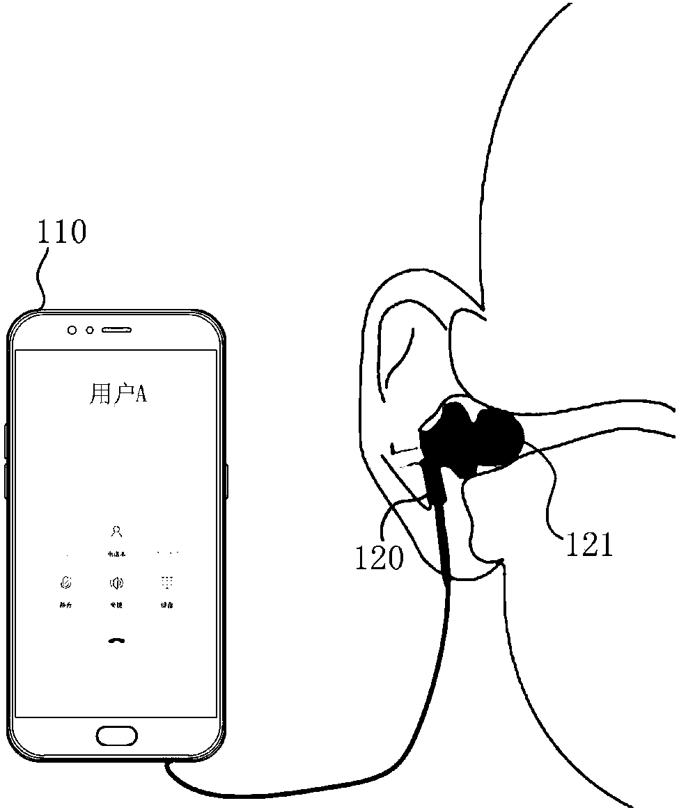
[0029] figure 1 It is a schematic diagram of the application environment of the signal switching method in an embodiment. The signal switching method in this embodiment is applied to devices with audio communication functions, such as figure 1 As shown, the application environment includes a terminal 110 and a headset 120 communicating with the terminal 110.
[0030] Wherein, the terminal 110 is in a communication connection with the headset 120. The types of the earphone 120 include, but are not limited to, in-ear earphones and earbud earphones. The terminal 110 and the earphone 120 may communicate in a wired or wireless manner to realize data transmission.
[0031] An audio signal can be played on the terminal 110, and the audio signal can be music, video audio, call sound, etc., and the audio signal played by the terminal 110 is transmitted to the user's ear through the earphone 120, so that the user can hear the sound. In the same way, the earphone 120 can also collect audio signals, which can be user voice and ambient sound. The audio signals collected by the earphone 120 are transferred to the terminal 110 for processing, and can be used for call voice, voice commands, audio noise reduction, and the like.
[0032] The earphone 120 includes an electroacoustic transducer 121. The electroacoustic transducer 121 is located at the tip of the earphone. When the tip of the earphone is positioned in the ear canal of the user, the electroacoustic transducer 121 outputs the audio signal played by the terminal 110 to In the user's ear canal. The electroacoustic transducer 121 includes a speaker and a microphone. The speaker is used to play audio signals sent by the terminal 110, and the microphone is used to record audio signals around the earphone 120. Optionally, the speaker and the microphone are an integrated structure.
[0033] figure 2 It is a schematic diagram of the internal structure of the terminal in an embodiment. The terminal 110 includes a processor, a memory, and a display screen connected through a system bus. Among them, the processor is used to provide computing and control capabilities to support the operation of the entire terminal 110. The memory is used to store data, programs, and/or instruction codes, etc., and at least one computer program is stored in the memory, and the computer program can be executed by the processor to implement the signal switching method suitable for the terminal 110 provided in the embodiment of the present application. The memory may include non-volatile storage media such as magnetic disks, optical disks, read-only memory (Read-Only Memory, ROM), or random-access-memory (Random-Access-Memory, RAM). For example, in one embodiment, the memory includes a non-volatile storage medium and internal memory. The non-volatile storage medium stores an operating system, a database, and a computer program. The database stores data related to the signal switching method provided in the above embodiments. The computer program can be executed by a processor to implement a signal switching method provided by each embodiment of the present application. The internal memory provides a cache operating environment for the operating system, database and computer program in the non-volatile storage medium. The display screen may be a touch screen, such as a capacitive screen or an electronic screen, for displaying interface information of the terminal 110. The display screen includes a screen on state and a screen off state. The terminal 110 may be a mobile phone, a tablet computer, or a personal digital assistant or a wearable device.
[0034] Those skilled in the art can understand, figure 2 The structure shown in is only a block diagram of part of the structure related to the solution of the present application, and does not constitute a limitation on the terminal 110 to which the solution of the present application is applied. The specific terminal 110 may include more or Fewer parts, or combine some parts, or have a different arrangement of parts.
[0035] Such as image 3 Shown is a flow chart of the signal switching method in one embodiment. The signal switching method in this embodiment runs on figure 1 Take the terminal and/or headset as an example in the description. The signal switching method is applied to a device with audio communication function, the device includes such as Figure 4 As shown in the audio processing circuit, the audio processing circuit includes a signal converter, a signal switching unit and at least two audio transceiver units. The signal switching party includes the following steps 302 to 306:
[0036] Step 302: Acquire audio signals received by at least two of the audio transceiver units.
[0037] Among them, the audio processing circuit is used to realize the signal conversion process, for example, the audio processing circuit processes the uplink voice and the downlink voice during a voice call. When the audio processing circuit processes the uplink voice, it converts the sound wave signal into an electrical signal and transmits it to the line Medium; When the audio processing circuit processes the downlink voice, it converts the electrical signal into a sound wave signal and transmits it to the speaker. The audio transceiver unit is used to collect audio signals or send (play) audio signals. Optionally, the audio transceiver unit includes a speaker and a microphone. The speaker can convert electrical signals into acoustic signals, and the microphone can convert audio signals into electrical signals. That is, the audio processing circuit implements the audio signal transceiving process through the audio transceiving unit.
[0038] When the audio signal is processed by the audio processing circuit, the audio signals received by at least two audio transceiver units are acquired to obtain at least two audio signals.
[0039] Step 304: Connect at least two channels of the audio signals to the signal converter through the signal switching unit.
[0040] Wherein, the signal switching unit is used to switch between multiple audio signals, and the signal switching unit adopts a single-pole multi-throw switch. Optionally, the signal switching unit may also be a radio frequency switch. The signal converter is used to convert analog and digital signals. The signal converter includes ADC (Analog-to-Digital Converter) and DAC (Digital-to-Analog Converter). When the signal When the converter is an ADC, the analog signal can be converted into a digital signal, and when the signal converter is a DAC, the digital signal can be converted into an analog signal.
[0041] Specifically, the signal switching unit includes a control terminal and at least two switching terminals, the control terminal is connected to the signal converter, and the switching terminal is connected to each audio transceiver unit in a one-to-one correspondence. The audio signal is connected to the signal converter through the signal switching unit, so that a signal transmission path is formed between the signal converter and at least two audio transceiver units.
[0042] Step 306: Control the signal switching unit to switch the signal transmission path according to a preset switching strategy, so that the signal converter performs signal conversion on at least two channels of the audio signal.
[0043] Specifically, when the signal converter and the two audio transceiving units form at least two signal transmission paths, the signal switching unit may be controlled to sequentially switch between the two signal transmission paths according to a preset time interval. Among them, in order to make the signal more continuous, the switching interval is set to time division switching. The time division switching method divides the time into several non-overlapping time slots, establishes different sub-channels from different time slots, and exchanges the network through time slots. The time slot movement of the signal is completed, thereby realizing the switching of audio signals between different signal transmission paths.
[0044] Optionally, the signal transmission path may also be switched according to the audio signal strength, the signal strength of the audio signal received by each audio transceiver unit is detected, and the signal switching unit is controlled to switch to the signal transmission path with the highest audio signal strength. For example, when accessing the audio signal collected by each audio transceiver unit, it is necessary to detect and record the signal strength of the current audio signal. The signal strength reflects the sound strength. Compare the signal strength of each audio signal and switch the signal. The switching end of the unit is connected to the signal transceiving unit corresponding to the audio signal with the highest signal strength.
[0045] The signal transmission path is switched by controlling the signal switching unit, so that the signal converter performs signal conversion on at least two audio signals. In this embodiment, the signal converter is an ADC, which converts at least two audio signals into electrical signals, where the audio signals are analog signals and the electrical signals are digital signals.
[0046] In the above signal switching method, by acquiring at least two audio signals received by the audio transceiving unit, at least two channels of the audio signal are connected to the signal converter through the signal switching unit, and the control station is controlled according to a preset switching strategy. The signal switching unit switches the signal transmission path, so that the signal converter performs signal conversion on at least two channels of the audio signal. Through the above method, the ADC in the circuit is reduced, the hardware cost of the ADC is saved, and the utilization of hardware resources is improved.
[0047] In one embodiment, the audio transceiver unit includes an electro-acoustic transducer, such as Figure 5 As shown, the acquiring audio signals received by at least two audio transceiver units includes the following steps 502 and/or step 504:
[0048] Step 502: Receive the audio signal obtained by the electroacoustic transducer on the terminal.
[0049] Specifically, the terminal has an electroacoustic transducer, which refers to a device used to receive electrical (or acoustic) input signals and convert them into acoustic (or electrical) output signals, such as speakers and microphones. And receiver etc. When performing audio communication through the terminal, the audio signal obtained by the electroacoustic transducer on the terminal is received. For example, when a call is made through the terminal, the microphone on the terminal collects the sound wave signal generated by the vibration of the user's vocal cord, and transmits the sound wave signal to the audio processing unit for signal conversion processing.
[0050] Step 504: When the terminal is in a communication connection with the earphone, receive the audio signal obtained by the electroacoustic transducer on the earphone.
[0051] When a headset is connected to the terminal, the audio signal sent from the terminal and the audio signal that the terminal needs to collect are all carried through the headset by default. When the audio processing circuit processes the audio signals collected by the signal transceiver unit, it receives the audio signals obtained by the electroacoustic transducer on the earphone. Wherein, the audio signal includes user voice and/or surrounding environment sound.
[0052] Specifically, the earphone includes an electro-acoustic transducer, and the electro-acoustic transducer can be used as a speaker to convert the electrical signal corresponding to the audio signal into a sound wave signal that the user can hear. At the same time, the electro-acoustic transducer is very sensitive to sound waves. When receiving the sound waves, it can cause the speaker cone to vibrate, and drive the coil connected to the cone to cut the magnetic field lines in the magnetic field of the permanent magnet, thereby generating a motion that follows the sound waves. The changing electric current (the phenomenon of generating electric current is called electromagnetic induction phenomenon in physics), and at the same time, the electromotive force of audio frequency will be output at both ends of the coil. Therefore, the electroacoustic converter can also collect audio signals. That is, the electroacoustic transducer can also be used as a microphone.
[0053] Electroacoustic transducers, although their types, functions or working conditions are different, they all include two basic components, namely the electrical system and the mechanical vibration system. Inside the electroacoustic transducer, the electrical system and the mechanical vibration system pass between Certain physical effects are interconnected to complete energy conversion.
[0054] Optionally, audio signals can also be collected through a microphone set in the headset. The microphone can be set on the headset housing or on the headset cable; it is understandable that the microphone can also be set near the user’s vocal cord. Any location in the vicinity is not limited in this embodiment.
[0055] In one embodiment, when a call is made through a headset, the user's voice is collected based on an electroacoustic transducer that plays an audio signal in the headset; where the electroacoustic transducer includes a left microphone and a right microphone. According to the left microphone and the right microphone on the headset, the left channel signal and the right channel signal are obtained respectively.
[0056] It is understandable that a headset usually includes a left-channel headset and a right-channel headset. When the electroacoustic transducer that plays the audio signal in the headset is used as a microphone to collect sound, the headset has a left microphone and a right microphone, and the left microphone The audio signal collected by the microphone is the left channel signal, and the audio signal collected by the right microphone is the right channel signal. Among them, the left channel signal is a sound wave signal collected by the left microphone simulating the hearing range of a human left ear, and the right channel signal is a sound wave signal collected by the right microphone simulating the hearing range of a human right ear.
[0057] Further, the electroacoustic transducer on the earphone transmits the collected left and right channel signals to the audio signal processing circuit, and the audio signal processing circuit controls the signal switching unit to control the left channel signal and the right channel signal according to a preset time interval. The channel signal is switched, so that the signal converter converts the left channel signal and the right channel signal collected by the earphone into an electrical signal for sending call information.
[0058] Optionally, the audio processing circuit may also be provided in the headset, and the headset further includes a processing chip, and the processing chip completes the audio signal processing process.
[0059] In one embodiment, such as Image 6 As shown, the signal switching method further includes the following steps 602 to 606:
[0060] Step 602: Obtain the electrical signal sent by the device, and obtain two audio signals after the electrical signal is converted by the signal converter.
[0061] The device includes a terminal and earphones connected in communication. When the audio signal is played through the audio processing circuit on the device, the electrical signal sent by the device is obtained, and the electrical signal is converted by a signal converter to obtain two audio signals. For example, when playing music through headphones, the terminal sends an electrical signal containing music information to a DAC, and the DAC converts the electrical signal containing music information into a left channel signal and a right channel signal for the user to listen to with both ears.
[0062] Step 604: Connect the two audio signals to the corresponding audio transceiver unit through the signal switching unit.
[0063] Specifically, the signal switching unit includes a control terminal and at least two switching terminals, the control terminal is connected to the signal converter, the switching terminal is connected to each audio transceiver unit in a one-to-one correspondence, and two audio signals are passed through The signal switching unit is respectively connected to the corresponding audio transceiver unit, so that a signal transmission path is formed between the signal converter and the two audio transceiver units. For example, the audio transceiver unit includes an electro-acoustic transducer on the earphone. The electro-acoustic transducer includes a left speaker and a right speaker. The left speaker and the right speaker are used to play the left channel signal and the right channel signal respectively, which are converted by DAC The resulting left channel signal and right channel signal are respectively transmitted to the signal transmission paths corresponding to the left speaker and the right speaker on the earphone.
[0064] Step 606: Control the signal switching unit to switch the two channels of audio signals according to the preset time interval, so that the two channels of audio signals are respectively used for audio playback through the corresponding audio transceiver unit.
[0065] Among them, in order to make the signal more continuous, the switching interval is set to time division switching. The time division switching method divides the time into several non-overlapping time slots, establishes different sub-channels from different time slots, and exchanges the network through time slots. The time slot movement of the signal is completed, thereby realizing the switching of audio signals between different signal transmission paths. For example, if the preset time interval is 5ms, the signal switch will switch every 5ms. When playing music, the left channel signal and the right channel signal after DAC conversion will pass through the left speaker of the earphone at a time interval of 5ms. And the right speaker to switch between the left and right channels.
[0066] In the signal switching method provided by this embodiment, the electrical signal sent by the device is obtained, the electrical signal is converted by the signal converter to obtain two audio signals, and the two audio signals are passed through the The signal switching unit accesses the corresponding audio transceiver unit, and controls the signal switching unit to switch the two audio signals according to a preset time interval, so that the two audio signals are respectively played through the corresponding audio transceiver unit , Reducing the use of DAC in the circuit, saving the hardware cost of the DAC, and improving the utilization of hardware resources.
[0067] It should be understood that, although the steps in the flowchart corresponding to the foregoing embodiment are displayed in sequence as indicated by the arrows, these steps are not necessarily executed in sequence in the order indicated by the arrows. Unless specifically stated in this article, the execution of these steps is not strictly restricted in order, and these steps can be executed in other orders. and, Figure 3-6 At least part of the steps in may include multiple sub-steps or multiple stages. These sub-steps or stages are not necessarily executed at the same time, but can be executed at different times, and the order of execution of these sub-steps or stages is not necessarily It is performed sequentially, but may be performed alternately or alternately with at least a part of other steps or sub-steps or stages of other steps.
[0068] Such as Figure 7 As shown, in one embodiment, a signal switching device is provided, which includes: a signal acquisition module 710, a signal connection module 720, and a signal switching module 730.
[0069] The signal acquisition module 710 is configured to acquire audio signals received by at least two of the audio transceiver units.
[0070] The signal connection module 720 is configured to connect at least two channels of the audio signals to the signal converter through the signal switching unit.
[0071] The signal switching module 730 is configured to control the signal switching unit to switch the signal transmission path according to a preset switching strategy, so that the signal converter performs signal conversion on at least two channels of the audio signals.
[0072] The above-mentioned signal switching device acquires at least two audio signals received by the audio transceiver unit through the signal acquisition module 710, and the signal connection module 720 connects at least two channels of the audio signals to the signal converter through the signal switching unit The signal switching module 730 controls the signal switching unit to switch the signal transmission path according to a preset switching strategy, so that the signal converter performs signal conversion on at least two channels of the audio signal. Through the above device, the signal converter in the circuit is reduced, the hardware cost of the signal converter is saved, and the utilization rate of hardware resources is improved.
[0073] In one embodiment, the signal acquisition module 710 is further configured to receive audio signals acquired by the electro-acoustic transducer on the terminal; and/or when the terminal is in a communication connection with the headset, receive the electro-acoustic transducer on the headset. The audio signal obtained by the energy sensor. Wherein, the audio signal includes user voice and/or surrounding environment sound.
[0074] In one embodiment, the signal acquisition module 710 is further configured to collect the user's voice based on the electroacoustic transducer that plays the audio signal in the earphone when a call is made through the headset; the electroacoustic transducer includes a left microphone and a right microphone. Microphone; according to the left microphone and right microphone on the headset to obtain the left channel signal and the right channel signal respectively.
[0075] In one embodiment, the signal switching module 730 is further configured to control the signal switching unit to switch the left channel signal and the right channel signal according to a preset time interval; the signal converter converts the signal collected by the earphone The left channel signal and the right channel signal are converted into electrical signals used to send call information.
[0076] In one embodiment, the signal acquisition module 710 is also used to acquire the electrical signal sent by the device, and the electrical signal is converted by the signal converter to obtain two audio signals; the signal connection module 720 is also used to The two audio signals are connected to the corresponding audio transceiver unit through the signal switching unit; the signal switching module 730 is further configured to control the signal switching unit to switch the two audio signals according to a preset time interval, The audio signals of the two channels are respectively played through the corresponding audio transceiver unit.
[0077] In one embodiment, the signal acquisition module 710 is further configured to send an electrical signal containing music information to a signal converter when the device is playing music; the signal converter converts the music information The electrical signal is converted into a left channel signal and a right channel signal for the user to listen to with both ears.
[0078] Based on the above embodiment, the signal converter includes an analog-to-digital converter and a digital-to-analog converter.
[0079] The division of each module in the above-mentioned signal switching device is only for illustration. In other embodiments, the signal switching device can be divided into different modules as needed to complete all or part of the functions of the above-mentioned signal switching device.
[0080] For the specific limitation of the signal switching device, please refer to the above limitation of the signal switching method, which will not be repeated here. Each module in the above-mentioned signal switching device can be implemented in whole or in part by software, hardware, and a combination thereof. The above-mentioned modules may be embedded in the form of hardware or independent of the processor in the computer equipment, or may be stored in the memory of the computer equipment in the form of software, so that the processor can call and execute the operations corresponding to the above-mentioned modules.
[0081] The implementation of each module in the signal switching device provided in the embodiment of the present application may be in the form of a computer program. The computer program can be run on a terminal or server. The program module constituted by the computer program can be stored in the memory of the terminal or server. When the computer program is executed by the processor, it implements the steps of the signal switching method described in the embodiments of the present application.
[0082] The embodiment of the present application also provides a headset. The headset includes an electro-acoustic transducer, a memory, a processor, and a computer program stored in the memory and running on the processor. The processor and the electro-acoustic converter The energy device and the memory are electrically connected, and the processor implements the signal switching methods described in the foregoing embodiments when the processor executes the computer program. Wherein, the electroacoustic transducer includes a speaker and a microphone, the speaker is used for playing audio signals, and the microphone is used for collecting user voice and/or ambient sound. Optionally, the speaker and the microphone are an integrated structure.
[0083] The embodiment of the present application also provides a computer-readable storage medium. One or more non-volatile computer-readable storage media containing computer-executable instructions, when the computer-executable instructions are executed by one or more processors, cause the processors to execute as described in the foregoing embodiments The described signal switching method.
[0084] The embodiment of the present application also provides a computer program product. A computer program product containing instructions, when it runs on a computer, causes the computer to execute the signal switching methods described in the foregoing embodiments.
[0085] The embodiment of the present application also provides a terminal device. The terminal includes an audio processing circuit, the audio processing circuit includes a signal converter, a signal switching unit and at least two audio transceiver units, the signal switching unit includes a control terminal and at least two switching terminals, the control terminal and the The signal converter is connected, and the switching end is connected to each audio transceiver unit in a one-to-one correspondence, so that a signal transmission path is formed between the signal converter and at least two audio transceiver units.
[0086] Such as Figure 8 As shown, for ease of description, only the parts related to the embodiments of the present application are shown. For specific technical details that are not disclosed, please refer to the method part of the embodiments of the present application. The terminal can be any terminal device including a mobile phone, a tablet computer, a PDA (Personal Digital Assistant), a POS (Point of Sales), a car computer, a wearable device, etc., taking the terminal as a mobile phone as an example:
[0087] Figure 8 It is a block diagram of a part of the structure of a mobile phone related to the computer equipment provided in the embodiments of the present application. reference Figure 8 The mobile phone includes: a radio frequency (RF) circuit 810, a memory 820, an input unit 830, a display unit 840, a sensor 850, an audio circuit 860, a wireless fidelity (WiFi) module 870, a processor 880, and a power supply 890 and other parts. Those skilled in the art can understand, Figure 8 The structure of the mobile phone shown does not constitute a limitation on the mobile phone, and may include more or less components than shown, or a combination of some components, or a different component arrangement.
[0088] Among them, the RF circuit 810 can be used to receive and send signals during information transmission or communication, and can receive downlink information from the base station and send it to the processor 880 for processing; and can also send uplink data to the base station. Generally, the RF circuit includes, but is not limited to, an antenna, at least one amplifier, a transceiver, a coupler, a low noise amplifier (LNA), a duplexer, and the like. In addition, the RF circuit 810 can also communicate with the network and other devices through wireless communication. The above-mentioned wireless communication can use any communication standard or protocol, including but not limited to Global System of Mobile communication (GSM), General Packet Radio Service (GPRS), Code Division Multiple Access (Code Division Multiple Access). Access, CDMA), Wideband Code Division Multiple Access (WCDMA), Long Term Evolution (LTE), Email, Short Messaging Service (SMS), etc.
[0089] The memory 820 may be used to store software programs and modules. The processor 880 executes various functional applications and data processing of the mobile phone by running the software programs and modules stored in the memory 820. The memory 820 may mainly include a program storage area and a data storage area, where the program storage area may store an operating system, an application program required by at least one function (such as an application program for a sound playback function, an application program for an image playback function, etc.), etc.; The data storage area can store data (such as audio data, address book, etc.) created according to the use of the mobile phone. In addition, the memory 820 may include a high-speed random access memory, and may also include a non-volatile memory, such as at least one magnetic disk storage device, a flash memory device, or other volatile solid-state storage devices.
[0090] The input unit 830 can be used to receive inputted digital or character information, and generate key signal input related to user settings and function control of the mobile phone 800. Specifically, the input unit 830 may include a touch panel 831 and other input devices 832. The touch panel 831, also called a touch screen, can collect the user's touch operations on or near it (for example, the user uses any suitable objects or accessories such as fingers, stylus, etc.) on the touch panel 831 or near the touch panel 831 Operation), and drive the corresponding connection device according to the preset program. In one embodiment, the touch panel 831 may include two parts: a touch detection device and a touch controller. Among them, the touch detection device detects the user's touch position, and detects the signal brought by the touch operation, and transmits the signal to the touch controller; the touch controller receives the touch information from the touch detection device, converts it into contact coordinates, and then sends it To the processor 880, and can receive and execute the commands sent by the processor 880. In addition, the touch panel 831 can be implemented in multiple types such as resistive, capacitive, infrared, and surface acoustic wave. In addition to the touch panel 831, the input unit 830 may also include other input devices 832. Specifically, the other input device 832 may include, but is not limited to, one or more of a physical keyboard, function keys (such as volume control keys, switch keys, etc.).
[0091] The display unit 840 may be used to display information input by the user or information provided to the user and various menus of the mobile phone. The display unit 840 may include a display panel 841. In an embodiment, the display panel 841 may be configured in the form of a liquid crystal display (Liquid Crystal Display, LCD), an organic light-emitting diode (Organic Light-Emitting Diode, OLED), etc. In one embodiment, the touch panel 831 can cover the display panel 841. When the touch panel 831 detects a touch operation on or near it, it transmits it to the processor 880 to determine the type of the touch event. The type of touch event provides corresponding visual output on the display panel 841. Although in Figure 8 The touch panel 831 and the display panel 841 are used as two independent components to realize the input and input functions of the mobile phone. However, in some embodiments, the touch panel 831 and the display panel 841 can be integrated to realize the input of the mobile phone. And output function.
[0092] The mobile phone 800 may also include at least one sensor 850, such as a light sensor, a motion sensor, and other sensors. Specifically, the light sensor may include an ambient light sensor and a proximity sensor. The ambient light sensor can adjust the brightness of the display panel 841 according to the brightness of the ambient light. The proximity sensor can close the display panel 841 and/or when the mobile phone is moved to the ear. Or backlight. Motion sensors can include acceleration sensors. The acceleration sensors can detect the magnitude of acceleration in various directions. When stationary, the magnitude and direction of gravity can be detected. It can be used to identify mobile phone gestures (such as horizontal and vertical screen switching) and vibration recognition related functions (such as Pedometer, percussion), etc.; in addition, the mobile phone can also be equipped with other sensors such as gyroscope, barometer, hygrometer, thermometer, infrared sensor, etc.
[0093] The audio circuit 860, the speaker 861 and the microphone 862 can provide an audio interface between the user and the mobile phone. The audio circuit 860 can transmit the electric signal after the conversion of the received audio data to the speaker 861, and the speaker 861 converts it into a sound signal for output; on the other hand, the microphone 862 converts the collected sound signal into an electric signal, and the audio circuit 860 After being received, it is converted into audio data, and then processed by the audio data output processor 880, and then sent to another mobile phone via the RF circuit 810, or the audio data is output to the memory 820 for subsequent processing.
[0094] WiFi is a short-distance wireless transmission technology. The mobile phone can help users send and receive emails, browse web pages, and access streaming media through the WiFi module 870. It provides users with wireless broadband Internet access. although Figure 8 The WiFi module 870 is shown, but it is understandable that it is not a necessary component of the mobile phone 800 and can be omitted as required.
[0095] The processor 880 is the control center of the mobile phone. It uses various interfaces and lines to connect various parts of the entire mobile phone. It executes by running or executing software programs and/or modules stored in the memory 820, and calling data stored in the memory 820. Various functions and processing data of the mobile phone can be used to monitor the mobile phone as a whole. In one embodiment, the processor 880 may include one or more processing units. In one embodiment, the processor 880 may integrate an application processor and a modem processor, where the application processor mainly processes an operating system, a user interface, and an application program; the modem processor mainly processes wireless communication. It can be understood that the foregoing modem processor may not be integrated into the processor 880.
[0096] The mobile phone 800 also includes a power supply 890 (such as a battery) for supplying power to various components. Preferably, the power supply can be logically connected to the processor 880 through a power management system, so that functions such as charging, discharging, and power management can be managed through the power management system.
[0097] In an embodiment, the mobile phone 800 may also include a camera, a Bluetooth module, and the like.
[0098] In the embodiments of the present application, the processor 880 included in the mobile terminal executes the computer program stored in the memory to implement the signal switching methods described in the foregoing embodiments.
[0099] When the computer program running on the processor is executed, the signal converter in the circuit is reduced, the hardware cost of the signal converter is saved, and the utilization rate of hardware resources is improved.
[0100] Any reference to memory, storage, database or other media used in this application may include non-volatile and/or volatile memory. Suitable non-volatile memory may include read only memory (ROM), programmable ROM (PROM), electrically programmable ROM (EPROM), electrically erasable programmable ROM (EEPROM), or flash memory. Volatile memory may include random access memory (RAM), which acts as external cache memory. As an illustration and not a limitation, RAM is available in many forms, such as static RAM (SRAM), dynamic RAM (DRAM), synchronous DRAM (SDRAM), double data rate SDRAM (DDR SDRAM), enhanced SDRAM (ESDRAM), synchronous Link (Synchlink) DRAM (SLDRAM), memory bus (Rambus) direct RAM (RDRAM), direct memory bus dynamic RAM (DRDRAM), and memory bus dynamic RAM (RDRAM).
[0101] The above-mentioned embodiments only express several implementation manners of the present application, and their description is relatively specific and detailed, but they should not be understood as a limitation to the patent scope of the present application. It should be pointed out that for those of ordinary skill in the art, without departing from the concept of this application, several modifications and improvements can be made, and these all fall within the protection scope of this application. Therefore, the scope of protection of the patent of this application shall be subject to the appended claims.

PUM

no PUM

Description & Claims & Application Information

We can also present the details of the Description, Claims and Application information to help users get a comprehensive understanding of the technical details of the patent, such as background art, summary of invention, brief description of drawings, description of embodiments, and other original content. On the other hand, users can also determine the specific scope of protection of the technology through the list of claims; as well as understand the changes in the life cycle of the technology with the presentation of the patent timeline. Login to view more.

Similar technology patents

Classification and recommendation of technical efficacy words

  • Reduce hardware costs

Method and device for monitoring vehicle state and driving behavior

ActiveCN103942851AReduce hardware costs
Owner:BEIJING TRANSILINK INFORMATION TECH

Projection system used for presenting stereoscopic image and method thereof

InactiveCN101738737Asave institutional spaceReduce hardware costs
Owner:纬联电子科技(中山)有限公司 +1

System and method for realizing multi-card multi-standby mobile phone function by virtual method

ActiveCN102065161ASmall space volumeReduce hardware costs
Owner:SHENZHEN SANG FEI CONSUMER COMM CO LTD
Why Eureka
Try Eureka