Mixing bowl having suction cup

A bottom surface and structure technology, applied in the field of mixing bowls, can solve problems such as suction cups being obstructed

Inactive Publication Date: 2018-08-14
KEEEPER GMBH
View PDF1 Cites 0 Cited by
  • Summary
  • Abstract
  • Description
  • Claims
  • Application Information

AI Technical Summary

Problems solved by technology

However, the suction cup is in the way when the plate should not be attached to the seating surface (e.g. when it should be free to move or when it is being transferred)

Method used


Image

  • Mixing bowl having suction cup
  • Mixing bowl having suction cup
  • Mixing bowl having suction cup

Examples


Embodiment Construction

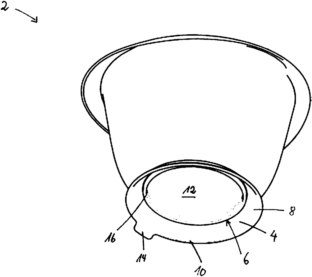
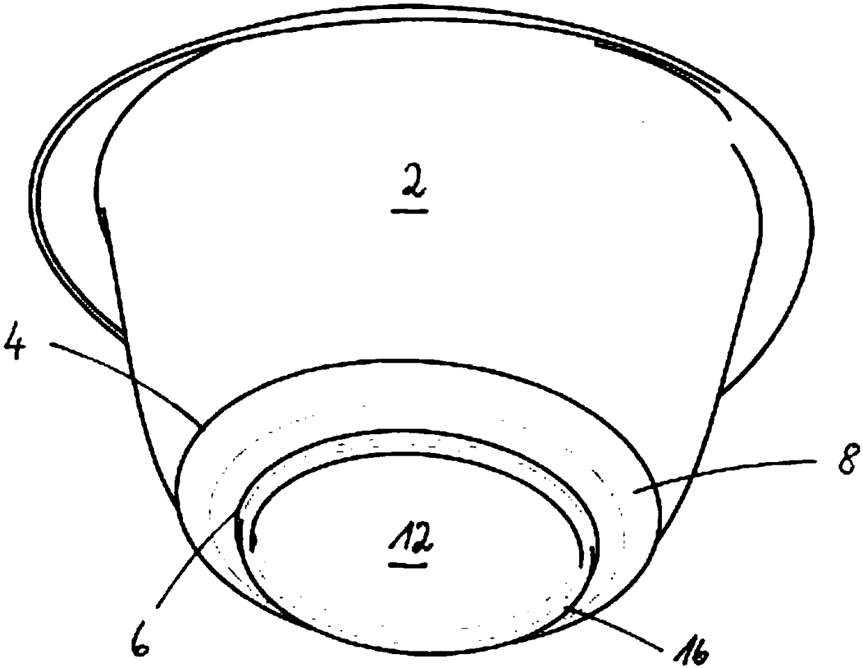
[0025] exist figure 1 The view from below shows mixing bowl 2 in . From this view, the sealing ring 4 can be clearly seen, which is connected with the mixing bowl 2 in a gas-tight manner with its inner edge region. The sealing ring 4 has a movable lip 8 which extends radially outwards from the edge region 6 . exist figure 1 In the relaxed position shown in , the lip, which is designed as a flat seal in this example, is oriented obliquely downwards.

[0026] On its underside, the movable lip has an annular bearing surface 10 , which begins at the outer edge of the movable lip 8 and which can increase inward according to the load acting on the movable lip 8 . In this embodiment, the bearing surface 10 is an annular surface.

[0027] In this exemplary embodiment, the edge region 6 of the sealing ring 4 is arranged on the outer edge of the bottom surface 12 of the mixing bowl 2 . Thus, the bottom surface 12 has a larger radius and covers a relatively larger area. Since the s...


PUM


Abstract

The invention relates to a mixing bowl (2) made from a plastics material, having a setup element of elastic material that on the base side is connected to the mixing bowl (2). The setup element provides a placing face. In order to create a mixing bowl in which a large negative pressure can be generated and in which an adsorption element has a better sealing effect, the following suggestion is made, ie, the setup element is configured as an encircling annular seal (4), the peripheral region (6) of the annular seal points in the radial direction inward and is connected to the bottom side of themixing bowl (2) air-tightly, wherein a lip (8) of the annular seal that in a load-dependent manner is movable between various positions extends from the inwardly pointing peripheral region (6) at least partially in a radial direction toward the outside, the lower side of the movable lip (8) in portions forming the placing face (10) by way of which the mixing bowl (2) in at least one position of the movable lip (8) stands on a setup surface (18), and the annular seal (4) conjointly with the bottom side (12) of the mixing bowl (2) forms a suction cup which delimits a cavity (20) that varies in size depending on the position of the movable lip (8).

Description

technical field [0001] The invention relates to a mixing bowl according to the preamble of claim 1 . Background technique [0002] A mixing bowl is known, for example, from DE 20 2009 009 198 U1. In order to be able to place the mixing bowl more slip-resistant on the work surface, it is proposed that the bottom surface of the ring-shaped surrounding seal is provided with a lip in each case at its inner and outer lower edges, which are defined between them. A cavity that creates a negative pressure on a smooth seating surface. Due to the negative pressure in the cavity, the mixing bowl is pressed onto the mounting surface and can no longer be unintentionally moved so easily during mixing. [0003] Since the cavity has only a small volume, the negative pressure that can be generated in this way is only relatively small. Furthermore, the lip has only a small material thickness, so that it fails in the case of minor damage and no longer reliably seals the cavity in the case o...

Claims


Application Information

Patent Timeline
Patent Type & Authority Applications(China)
IPC IPC(8): A47G19/02A47G19/10F16B47/00
CPCA47G29/093A47J43/0727F16B47/00A47G19/02A47G19/10B01F35/43A47J47/00B65D25/20B65D2313/06
Inventor 艾利克斯·达姆勒弗洛里安·M·威特约翰娜·柯尼希贝格马修·赫克索思腾·普拉特安德鲁·费里尔
Owner KEEEPER GMBH
Why Eureka
Try Eureka