Molten iron non-pollution electromagnetic slag conglomeration method

A non-polluting, molten iron technology, applied in the field of smelting technology, to eliminate dead ends of slag scavenging, shorten slag scavenging time, and reduce slag scavenging actions

Inactive Publication Date: 2018-08-14
ANGANG STEEL CO LTD
View PDF9 Cites 4 Cited by
  • Summary
  • Abstract
  • Description
  • Claims
  • Application Information

AI Technical Summary

Problems solved by technology

However, there are no relevant reports on the accumulation of molten iron slag

Method used


Image

  • Molten iron non-pollution electromagnetic slag conglomeration method
  • Molten iron non-pollution electromagnetic slag conglomeration method

Examples


Embodiment 1

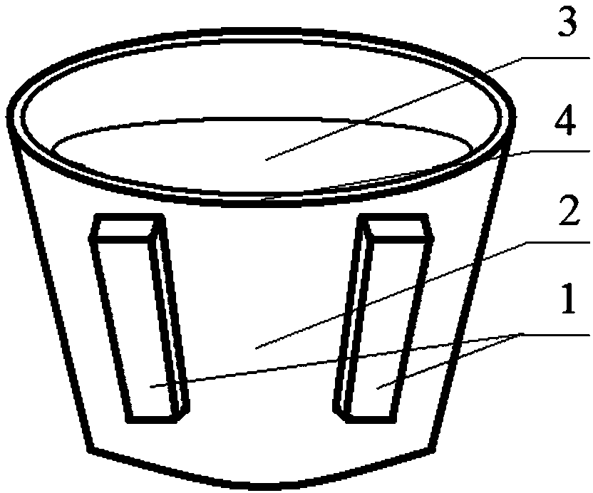
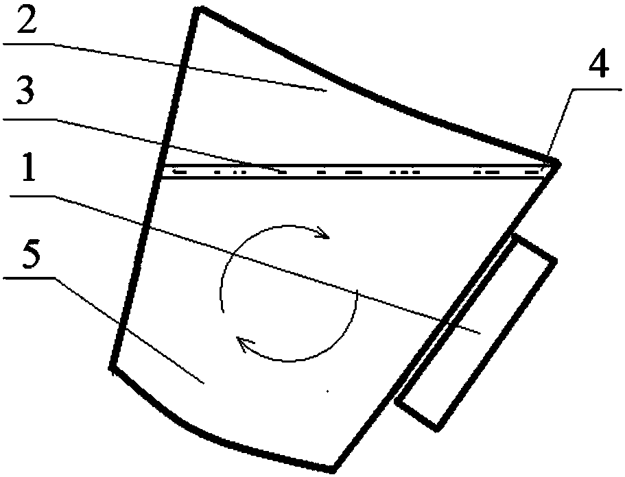
[0021] 1. Tilt the 100-ton molten iron tank 2 to the slag removal position to prepare for slag removal.

[0022] 2. Place a traveling wave magnetic field slag accumulator 1 with a power of 200kW and a frequency of 10Hz on both sides of the slag outlet 4 of the molten iron tank 2, and use the specific circulation generated by the molten iron 5 to separate the corners of the molten iron tank 2. The removed slag 3 is brought to the vicinity of the slag outlet 4 of the molten iron tank 2.

[0023] 3. Separation of iron in slag. Continue to apply the traveling wave magnetic field for 1 minute after electromagnetic slag gathering, so that the mixture of slag and iron can stay in the traveling wave magnetic field for a longer period of time, so as to improve the separation efficiency of slag and iron and reduce the iron loss.

[0024] After that, the slag can be removed with a slag remover. After cleaning, the molten iron tank is ready to enter the next process.

[0025] The avera...

Embodiment 2

[0027] 1. Tilt the 100-ton molten iron tank 2 to the slag removal position to prepare for slag removal.

[0028] 2. Place a 300kW traveling wave magnetic field slag accumulator 1 with a frequency of 10Hz on both sides of the slag outlet 4 of the molten iron tank 2, and collect the slag 3 at the corners of the tank that is not easy to be mechanically removed through the flow of the molten iron 5 to the slag outlet 4 nearby.

[0029] After the desulfurization slag is gathered, use a slag remover to remove the slag. After cleaning, the molten iron tank is ready to enter the next process.

[0030] The average time for removing slag in Example 2 was reduced from 11 minutes / time to 8 minutes / time. The iron loss of slag removal per ton of steel is reduced from 15kg / t to 13kg / t.


PUM

PropertyMeasurementUnit
heightaaaaaaaaaa
widthaaaaaaaaaa
thicknessaaaaaaaaaa

Abstract

The invention provides a molten iron non-pollution electromagnetic slag conglomeration method. Travelling wave magnetic field slag conglomeration devices, each of which is formed by a coil, an iron core and a shell, is prepared; each shell is internally provided with the corresponding coil; each coil is internally provided with a cooling water pipe and is provided with the corresponding iron corewhich is connected with a two-phase or three-phase alternating current at the middle part; a molten iron tank is inclined to a slag skimming position to prepare slag skimming; the travelling wave magnetic field slag conglomeration devices are put on the two sides of a slag outlet of the molten iron tank respectively to push molten iron to generate a specific circumfluence, and slags, difficultly mechanically eliminated, at corner portions of the molten iron tank are brought to the nearby of the slag outlet of the molten iron tank; and a downward electromagnetic force applied to the molten ironis much larger than an electromagnetic force applied to the slags, so that iron in the slags is separated out to enter the molten iron, and separation of the iron in the slags is realized. The molteniron non-pollution electromagnetic slag conglomeration method provided by the invention can eliminate a slag skimming dead angle, reduces the slag skimming action, shortens the slag skimming time, improves the operation efficiency, promotes separation of the iron and the slags, reduces loss of the molten iron, lowers the production cost and can effectively reduce secondary pollution brought by air blowing, slag skimming and the like.

Description

technical field [0001] The invention belongs to the technical field of smelting technology, and in particular relates to a pollution-free electromagnetic slag gathering method for molten iron. Background technique [0002] The hot metal desulfurization process is being popularized and applied rapidly, but there are generally problems of large iron loss after desulfurization and dirty slag removal at the corners. From the perspective of production practice, the processed iron slag has the problems of high alkalinity and poor fluidity. The slag is scattered and broken, which results in a long time for slag removal. During the process of slag removal, a large amount of molten iron is lost along with the slag. Affect output and steel material consumption indicators. [0003] At present, the domestic treatment of slag after desulfurization mostly uses the mechanical slag removal method. The iron loss of slag removal by this method mainly comes from two aspects. Mouth overflows....

Claims


Application Information

Patent Timeline
Patent Type & Authority Applications(China)
IPC IPC(8): B22D43/00
CPCB22D43/005
Inventor 郭庆涛廖相巍贾吉祥万雪峰黄玉平朱晓雷唐雪峰邹焕李晓伟张宇
Owner ANGANG STEEL CO LTD
Why Eureka
Try Eureka