
Slide groove clamping mechanical arm device

A manipulator and chute technology, applied in the directions of manipulators, chucks, conveyor objects, etc., can solve the problems of large space occupation, complex manipulator structure design, affecting the stability of motion, etc., and achieve the effect of compact structure

Pending Publication Date: 2018-08-14
柳州璞智科技有限公司
View PDF0 Cites 0 Cited by
  • Summary
  • Abstract
  • Description
  • Claims
  • Application Information

AI Technical Summary

Problems solved by technology

In order to improve the efficiency of industrial production and processing, manipulators are often used to grip and move items. However, the existing manipulators cannot accurately complete the gripping of similar thin items such as books or files. The structural design of the manipulator is too complicated, resulting in an increase in cost
[0003] Existing manipulators cannot accurately realize the movement and gripping of thin objects—specifically, the positioning of the manipulator to the horizontal position and the gripping of thin objects cannot be accurately realized
However, there are also some manipulator devices that are relatively inflexible to use, occupy a large space, and often require manual operation by personnel, which is not easy to disassemble and maintain
[0004] Some traditional manipulators realize the movement of the manipulator through hydraulic pressure or air pressure. Due to the viscosity of the liquid and the compressibility of the gas, the stability of the movement is often affected, and the requirements for the matching accuracy of the components are also high, which will limit the manipulator. on the application

Method used


Image

  • Slide groove clamping mechanical arm device
  • Slide groove clamping mechanical arm device
  • Slide groove clamping mechanical arm device

Examples


Embodiment

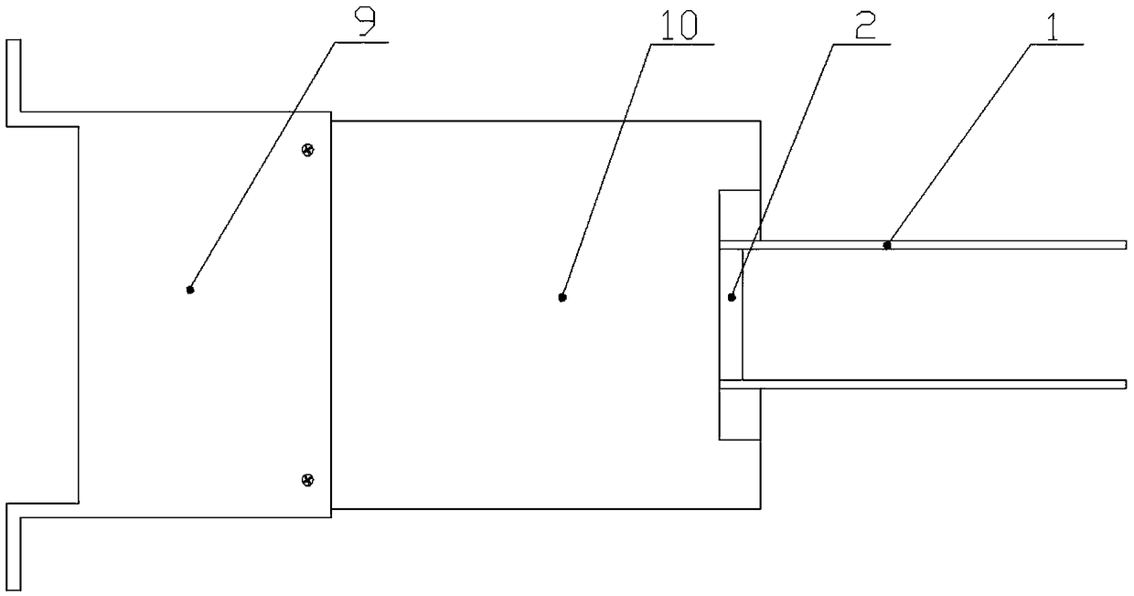
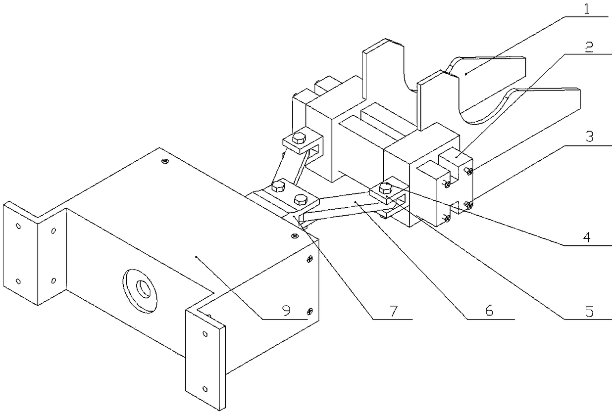
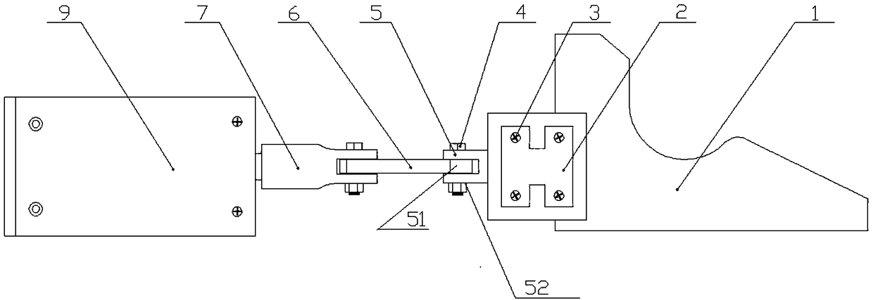
[0029] A kind of manipulator device for chute clamping, such as figure 1 , 2 , 3, 4, and 5, it is composed of a safety cover (10), a fixed housing (9), an electric cylinder (8), a rocker slider mechanism, and a slide chamber chute, wherein the safety cover (10) Installed in the fixed housing (9), such as Figure 9 As shown, the fixed housing (9) is designed in a convex shape, and is composed of a fixing screw hole (91), a cavity a (92), a U-shaped groove (93), and a fixing seat bottom (94). Four fixing screw holes (91) are designed on the bottom of the seat (94) for connecting the mechanical arm to realize the tight fixing of the mechanical arm and the fixed housing (9); the electric cylinder (8) is fixedly mounted on the fixed housing (9) The center of the electric cylinder (8) is equipped with a push-pull rod; the rocker slider mechanism is composed of a movable hinge seat (7), a connecting rod (6), a sliding hinge seat (5), and a connecting bolt (4). The two ends of desc...


PUM


Abstract

The invention discloses a slide groove clamping mechanical arm device. The slide groove clamping mechanical arm device comprises a safety hood, a fixed shell body, an electric cylinder, a rocking handle sliding block mechanism and a slide cavity slide groove. Compared with the existing structure, the change in structure of the invention is more compact, the fact that mechanical arm clamping platescan slide equidistantly at constant speed left and right inside slide grooves is realized due to the facts that the electric cylinder is symmetrically arranged and guiding and running distance rangelimiting of a round through hole in the safety hood are performed on a pushing rod, parallel translation is realized in the functionality aspect, and the slide groove clamping mechanical arm device ismade to have more stable smoothness.

Description

technical field [0001] The invention relates to a manipulator device for gripping a chute. Background technique [0002] In industry, manipulators can replace the heavy labor of people to realize the mechanization and automation of production. In order to improve the efficiency of industrial production and processing, manipulators are often used to grip and move items. However, the existing manipulators cannot accurately complete the gripping of similar thin items such as books or files. The structural design of the manipulator is too complicated, resulting in an increase in cost. [0003] Existing manipulators cannot accurately realize the movement and gripping of thin articles—specifically, they cannot accurately realize the positioning of the manipulator to the horizontal position and the gripping of thin articles. However, some manipulator devices are relatively inflexible to use, take up a lot of space, and often require manual operation by personnel, which is inconve...

Claims


Application Information

Patent Timeline
IPC IPC(8): B65G47/90B25J15/00B25J15/08B25J19/06
CPCB65G47/90B25J15/00B25J15/08B25J19/06
Inventor 林贤坤覃柏英李健刘岳飞许元洪朱书建
Owner 柳州璞智科技有限公司
Learn More