
A Correction Method of Single Point Laser Strain Calibration Error

A calibration error and laser technology, applied in the direction of optical devices, instruments, measuring devices, etc., can solve problems such as inaccurate assignment, calibration error, and affecting measurement and calibration results, and achieve the effect of improving assignment accuracy and ensuring accuracy

Active Publication Date: 2020-03-20
BEIJING CHANGCHENG INST OF METROLOGY & MEASUREMENT AVIATION IND CORP OF CHINA
View PDF9 Cites 0 Cited by
  • Summary
  • Abstract
  • Description
  • Claims
  • Application Information

AI Technical Summary

Problems solved by technology

Its disadvantage is that there is a calibration error at the measurement point C, which will lead to inaccurate assignment of the measured strain gauge pasted at point C and affect its measurement and calibration results

Method used


Image

  • A Correction Method of Single Point Laser Strain Calibration Error
  • A Correction Method of Single Point Laser Strain Calibration Error
  • A Correction Method of Single Point Laser Strain Calibration Error

Examples


Embodiment

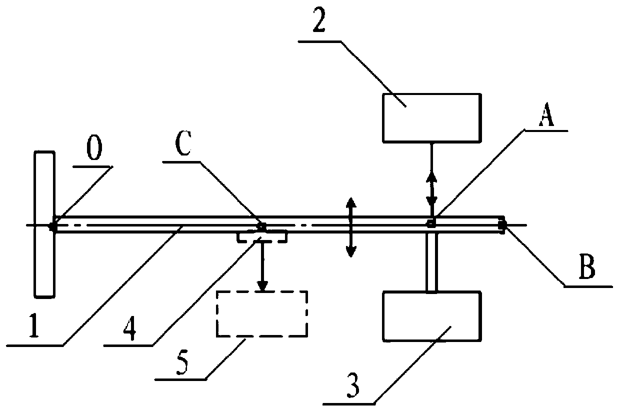
[0030] Such as figure 1 As shown, a single-point laser strain calibration error correction method can be used to correct the calibration error of measuring point C in the strain beam excitation measurement system. Wherein, the strain beam excitation measurement system includes a strain beam 1, a laser measurement device 2 and an excitation device 3; the intersection point of the axis of the laser beam output by the laser measurement device 2 and the axis of the strain beam 1 is point A, and the axis of the strain beam 1 The end point of the cantilever is point B, the measured strain gauge 4 is pasted on the strain beam 1, the intersection point of the axis passing through the center of the measured strain gauge 4 and the axis of the strain beam 1 is point C, and the constraint end point of the axis of the strain beam 1 is point O; The signal connection end of the strain gauge 4 is connected to the corresponding connection end of the strain gauge 5 . Wherein: the strain beam 1...


PUM


Abstract

The invention belongs to the strain measurement testing technical field and relates to a single-point laser strain calibration error correction method. The strain calibration error correction method is characterized in that the method includes the following steps that: excitation is carried out; measurement is carried out; the actual displacement value sequence di of a point A is calculated; the strain waveform sequence epsilonci(x) of a point C is calculated; and curve fitting is carried out. With the single-point laser strain calibration error correction method provided by the invention adopted, the calibration error of the measurement point C can be corrected, the accuracy of the value assignment of a tested strain gauge can be improved, and the accuracy of the measurement result of thetested strain gauge can be ensured.

Description

technical field [0001] The invention belongs to the technical field of strain measurement and testing, and relates to a method for correcting calibration errors of single-point laser strain measurement. Background technique [0002] Strain refers to the deformation behavior of solids and structures under loads such as force, moment, and pressure, as well as the deformation behavior of thermal expansion and contraction caused by environmental changes such as temperature. In normal temperature strain measurement, this kind of deformation refers specifically to elastic deformation, that is, the degree of deformation is monotonously corresponding to the change of load. When the load disappears, the deformation disappears. The strain is a physical quantity to quantitatively measure the magnitude of such strain. For strain measurement, people have various principles and methods, from classic resistive strain measurement, capacitive strain measurement, inductive strain measurement...

Claims


Application Information

Patent Timeline
Patent Type & Authority Patents(China)
IPC IPC(8): G01B11/16
CPCG01B11/16
Inventor 梁志国张大治尹肖孙浩琳
Owner BEIJING CHANGCHENG INST OF METROLOGY & MEASUREMENT AVIATION IND CORP OF CHINA
Learn More