Laser radar calibration device and calibration method based on space-time transformation

A laser radar and calibration device technology, applied in the direction of radio wave measurement systems, instruments, etc., can solve the problems of poor calibration accuracy, harsh calibration environment requirements, difficult to meet, etc., to eliminate the impact of accuracy, wide range of calibration distance, overcome Difficult to install effect

Active Publication Date: 2019-02-22
BEIJING HUA KEBO BOCHUANG TECH
View PDF4 Cites 9 Cited by
  • Summary
  • Abstract
  • Description
  • Claims
  • Application Information

AI Technical Summary

Problems solved by technology

[0006] 1) It is impossible to eliminate the individual differences of each pixel of the ToF sensor
The traditional calibration method, through the overall calibration method, does not consider the individual differences of the pixels, and generates the same error correction value after calibration of all the pixels, which cannot eliminate the individual measurement errors of different pixels
[0007] 2) Calibration accuracy is heavily dependent on the cooperation target used for calibration
[0008] 3) Strict requirements on the calibration environment
When calibrating the 3D area-array LiDAR ToF sensor in the traditional method, it is necessary to install a calibration cooperation target parallel to the image plane at different calibration distances and able to completely cover the image plane at this line-of-sight distance, without occlusion within the field of view. The required site and cooperative calibration target installation conditions are very harsh
At the same time, in order to obtain accurate calibration results, it is required to filter the ambient light in the same band during calibration. In practical applications, it is difficult to meet this calibration condition.
[0009] 4) The calibration operation is complicated, the process is cumbersome, and the efficiency is low
From the description of the above three points, it can be found that the calibration operation of the traditional calibration method is complicated and cumbersome, the calibration efficiency is low, and it is difficult to meet the requirements of productization
[0010] 5) Poor calibration accuracy
The calibration of the traditional calibration method is affected by uncertain factors such as individual differences in pixels, cooperative calibration goals, calibration environment, calibration process and steps, etc. The calibration results are highly random and inaccurate

Method used


Image

  • Laser radar calibration device and calibration method based on space-time transformation
  • Laser radar calibration device and calibration method based on space-time transformation
  • Laser radar calibration device and calibration method based on space-time transformation

Examples


Embodiment Construction

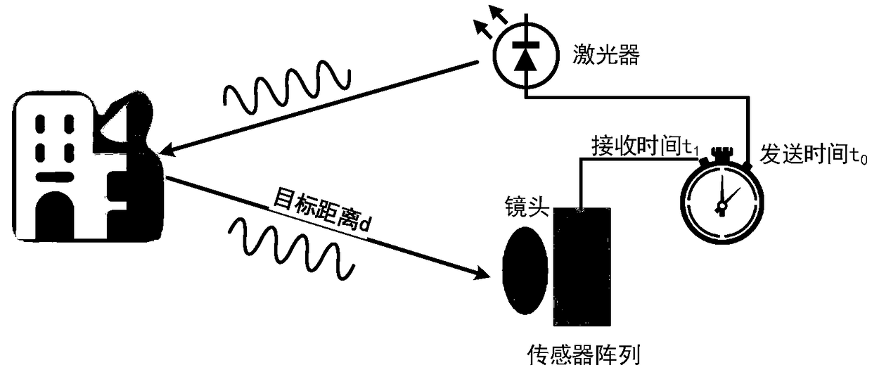
[0075] see figure 1 , ToF lidar ranging principle diagram, when ToF-based lidar starts ranging, it transmits signals to the target scene by controlling the laser, and the emission time is recorded as T 0 . After the signal is reflected by the target scene, it is transmitted to the sensor of the lidar and received by the sensor. The time when the sensor receives the signal is recorded as T 1 , the time difference between the transmitted signal and the received signal is (t 1 -t 0 ), combined with the speed of light c, the distance between the target scene and the lidar can be calculated:

[0076] d=c*(t1-t0) / 2

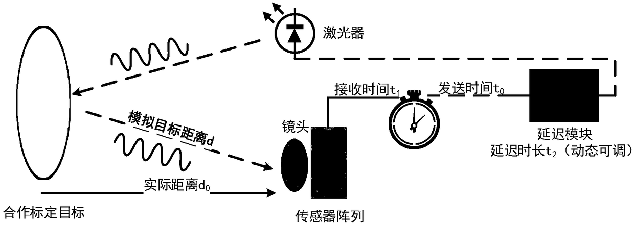
[0077] In order to make the calibration results more accurate, it is necessary to perform multiple calibrations at different distances. The traditional calibration method achieves calibration at different points by changing the actual physical distance between the cooperative calibration target and the 3D area array lidar. This calibration method requires a large T...


PUM


Abstract

The invention provides a laser radar calibration device based on space-time transformation, which is used for calibration of an all-solid-state three-dimensional planar array laser radar. The laser radar calibration device comprises a to-be-calibrated three-dimensional planar array laser radar installation portion, a cooperative calibration target installation part, an ambient light shielding boxbody, a directional reception active light source conduit and a time delay module, wherein the to-be-calibrated three-dimensional planar array laser radar installation portion, the cooperative calibration target installation part, the ambient light shielding box body, the directional reception active light source conduit and the time delay module are fixed by means of fixing screws and positioningholes, so as to form an integrated three-dimensional planar array laser radar calibration device. The invention further discloses a corresponding calibration method. the simple, convenient and rapidcalibration device and calibration method can perform rapid and precise calibration on the three-dimensional planar array laser radar, is high in calibration precision and wide in calibration distancerange, and does not require a special calibration environment and a special cooperative calibration target.

Description

technical field [0001] The invention relates to laser radar calibration technology, and in particular to a three-dimensional area array laser radar calibration device and calibration method based on space-time transformation. Background technique [0002] All-solid-state 3D area array lidar is an emerging 3D ranging imaging device. As the "eye" of intelligent equipment, it has been more and more widely used in industrial production, transportation and logistics, security monitoring and other fields. Applications such as sorting, robotic arm grabbing, AGV unmanned vehicle obstacle avoidance, car unmanned driving, 3D face recognition and behavior prediction provide real-time high-resolution distance information. [0003] Based on ToF (Time of Flight) all-solid-state three-dimensional area array lidar, by continuously sending light pulses to the target, and then using the sensor to receive the light returned from the object, the target distance can be obtained by detecting the ...

Claims


Application Information

Patent Timeline
Patent Type & Authority Applications(China)
IPC IPC(8): G01S7/497
Inventor 陈永然孙礼朋庄永良
Owner BEIJING HUA KEBO BOCHUANG TECH
Why Eureka
Try Eureka