
Direct-current fuse assembly device

A technology of fuses and main fuses, which is applied in the direction of emergency protection devices, electrical components, circuits, etc., can solve the problems of unsatisfactory operating efficiency and operating safety factor of switching operations, low operating safety factor, and cumbersome operating steps, etc., to achieve Realize the effect of easy operation, assembly and disassembly, large electrical isolation distance, and improvement of work efficiency

Pending Publication Date: 2018-08-14
GUANGDONG POWER GRID CO LTD +1
View PDF0 Cites 2 Cited by
  • Summary
  • Abstract
  • Description
  • Claims
  • Application Information

AI Technical Summary

Problems solved by technology

[0004] The present invention solves the problems of difficult operation, cumbersome operation steps, and low operational safety factor in the operation of DC fuses in the prior art, as well as technical defects that cannot meet the operational efficiency and operational safety requirements of switching operations. Provide a DC fuse assembly

Method used


Image

  • Direct-current fuse assembly device
  • Direct-current fuse assembly device

Examples


Embodiment 1

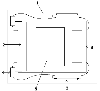
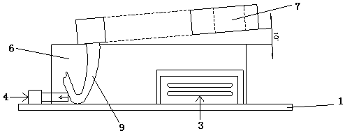
[0026] Such as figure 1 , figure 2 As shown, a DC fuse assembly device includes a base plate 1, a knife fuse switch 2, an alarm mount 3 and a travel switch 4; wherein, the knife fuse switch 2, the alarm mount 3, and the travel switch 4 are all Installed on the bottom plate 1; the alarm mounting base 3 is on both sides of the knife fuse switch 2; the travel switch 4 is connected to the knife fuse switch 2.

[0027] In the specific implementation process, the base plate 1 is used for fixedly installing the knife fuse switch 2, the alarm mounting seat 3 and the travel switch 4, and the whole device is installed at the wiring site; the knife fuse switch 2 is installed in the middle of the base plate 1, and the alarm is installed Seat 3 is installed on knife melting switch 2 both sides.

[0028] More specifically, the knife fuse switch 2 includes a plastic base 6, a box cover 7, an operating handle 8 and a crank arm 9; the plastic base 6 is installed on the bottom plate 1, and t...


PUM


Abstract

The invention relates to a direct-current fuse assembly device. The direct-current fuse assembly device comprises a base plate, a knife fuse switch, an alarm mounting seat and a travel switch, whereinthe knife fuse switch, the alarm mounting seat and the travel switch are all mounted on the base plate; the alarm mounting seat is mounted on both sides of the knife fuse switch; the travel switch isconnected with the knife fuse switch; and the knife fusion switch comprises a plastic base, a box cover, an operation handle and a crank arm. According to the direct-current fuse assembly device provided by the invention, a main fuse is placed in the box cover, thereby reducing the operational electric shock risk caused by the exposure of the outside of a direct-current fuse. Through the knife fuse switch, simple operation and assembly and disassembly functions of the main fuse are realized, and the electric isolation distance is relatively large to meet the requirements of safety operation.The six operation steps of a traditional direct-current fuse group are simplified into one step through arrangement of the stroke switch by means of the principle of mechanical sequential interruption, thereby greatly increasing the working efficiency.

Description

technical field [0001] The present invention relates to the technical field of fuse application, and more specifically, to a DC fuse assembly. Background technique [0002] At present, the DC fuses of the DC power supply system used in substations are large-capacity, large-volume, and exposed ceramic fuses. A set of DC fuses consists of positive and negative ceramic bases, positive and negative main fuses, and positive and negative fuses. Alarm and related secondary wiring components. The upper and lower ends of each ceramic fuse base have high-current metal spring bayonets, and the main fuse is connected or disconnected from the DC main circuit through the high-current metal spring bayonets; fuse alarms are installed on both sides of the main fuse body It is used to monitor the working status of the main fuse and send the alarm signal of the main fuse, and send the alarm signal to the remote place through the secondary wiring, but the installation distance on site is small...

Claims


Application Information

Patent Timeline
Patent Type & Authority Applications(China)
IPC IPC(8): H01H85/20H01H85/04
CPCH01H85/041H01H85/20
Inventor 温云龙刘德志袁拓来尹雁和罗其锋陈俊杜李志刘正高朱文吉田锋周惠琼陈忠敏陈诗杰胡振兴吴棉廷易婷李梦琪何伟杰
Owner GUANGDONG POWER GRID CO LTD
Learn More