Method for bonding adhesive tape, apparatus for bonding adhesive tape and method for transporting adhesive tape

A joining method and joining device technology, applied in the direction of conveyor objects, transportation and packaging, electrical components, etc., can solve problems such as interruption of operation of belt pasting devices

Inactive Publication Date: 2018-08-14
NITTO DENKO CORP
View PDF1 Cites 1 Cited by
  • Summary
  • Abstract
  • Description
  • Claims
  • Application Information

AI Technical Summary

Problems solved by technology

In the conventional device, it was necessary to stop the operation of the tape sticking device during the series of operations.

Method used


Image

  • Method for bonding adhesive tape, apparatus for bonding adhesive tape and method for transporting adhesive tape
  • Method for bonding adhesive tape, apparatus for bonding adhesive tape and method for transporting adhesive tape
  • Method for bonding adhesive tape, apparatus for bonding adhesive tape and method for transporting adhesive tape

Examples


Embodiment Construction

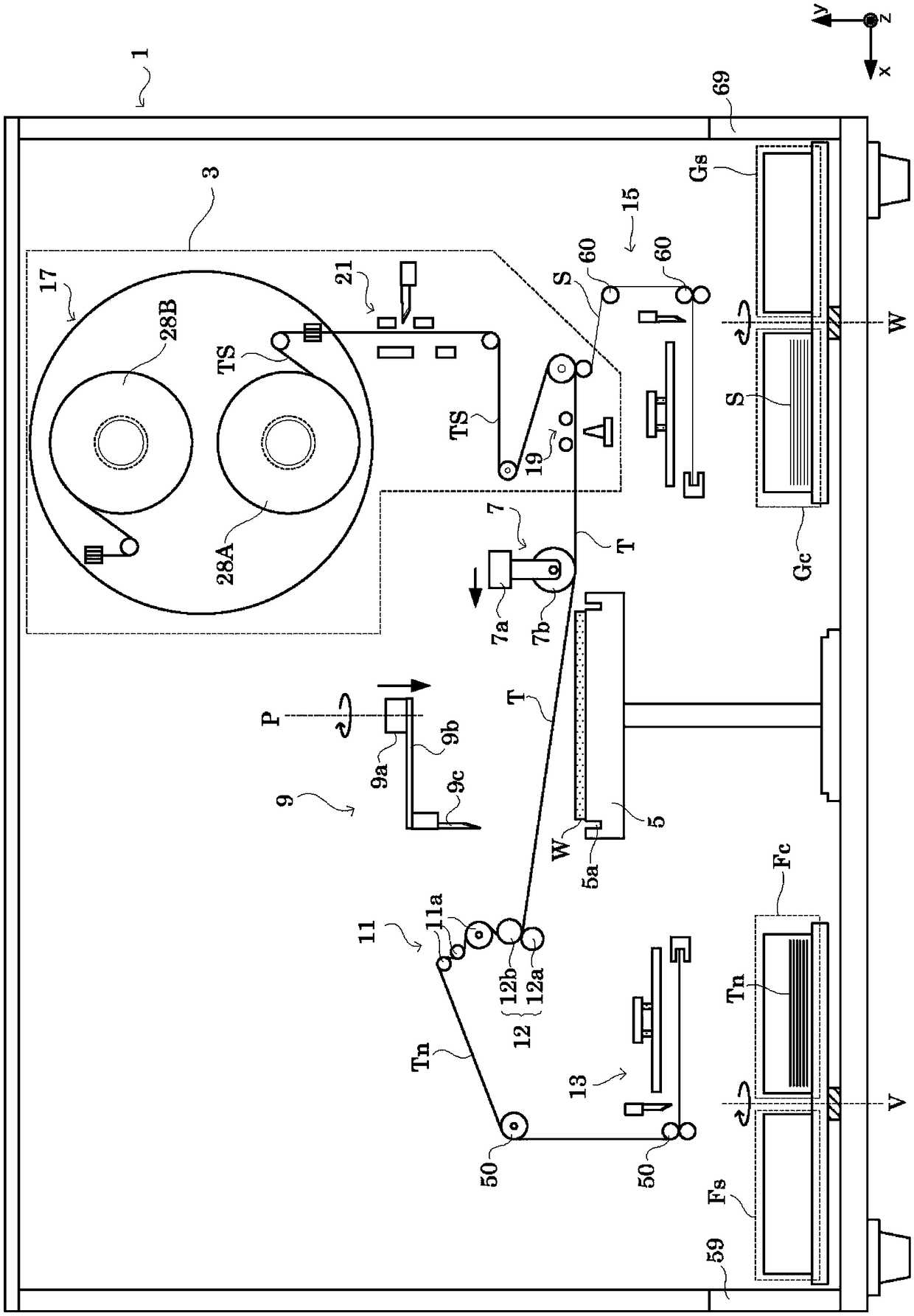
[0081] Hereinafter, embodiments of the present invention will be described with reference to the drawings. figure 1 It is a front view which shows the basic structure of the adhesive tape sticking apparatus 1 provided with the tape splicing apparatus of an Example. In addition, in the figure which shows the adhesive tape sticking apparatus 1, illustration about the support member which supports various structures, the drive member which drives various structures, etc. is abbreviate|omitted.

[0082] In the present embodiment, the case where a surface protection surface to be attached to various substrates such as semiconductor wafers (hereinafter simply referred to as "wafers") is supplied in a longitudinal shape to which a separator S is bonded is described as an example. Use the adhesive tape T and cut it into a specified shape on the downstream side. That is, in this embodiment, the lengthwise adhesive tapes are joined to each other.

[0083] In addition, in this embodim...


PUM


Abstract

The invention provides a method for bonding an adhesive tape, an apparatus for bonding an adhesive tape, and a method for transporting an adhesive tape, which can reliably bond the ends of an adhesivetape to each other and perform various kinds of handling even if the adhesive tape has strong adhesive force. A push-out member (33) protrudes a part of the adhesive tape (Tp) out of a long adhesivetape (T) in a direction (R) substantially perpendicular to a release direction (L). A pressing roller (35) presses the protruding adhesive tape (Tp) to make a part of the adhesive tape (T) as a gripping portion. Since the gripping portion protrudes by a predetermined length in the direction (R) at a predetermined position (Tf), the gripping portion can be easily and reliably held to operate the adhesive tape (T). In addition, since the length of the gripping portion in the release direction (L) is very short, it is possible to improve the positional accuracy of the region where handling is performed on the long adhesive tape by holding the gripping portion for handling, and it is possible to apply a large force to the limited region of the adhesive tape (T).

Description

technical field [0001] The present invention relates to bonding another adhesive tape to the rear end of the preceding adhesive tape in the process of supplying an adhesive tape to be attached to various substrates such as semiconductor wafers, LEDs (Light emitting diodes), and electronic circuits. The operation of the front end is exemplified by the adhesive tape splicing method, adhesive tape splicing device, and adhesive tape conveying method. Background technique [0002] Circuit patterns of a plurality of elements are formed on the surface of a semiconductor wafer (hereinafter, appropriately referred to as “wafer”). For example, bumps and fine circuits are formed on the wafer surface. Therefore, in order to prevent contamination and damage of the circuit surface during back grinding and transportation, a protective adhesive tape is attached to the surface of the wafer. [0003] Here, a conventional configuration of a tape sticking device used to stick an adhesive tape...

Claims


Application Information

Patent Timeline
Patent Type & Authority Applications(China)
IPC IPC(8): H01L21/67H01L21/677
CPCH01L21/67132H01L21/6773H01L21/6836H01L21/02
Inventor 奥野长平
Owner NITTO DENKO CORP
Why Eureka
Try Eureka