
Flexible direct current transmission system

A power transmission system, flexible direct current technology, applied in the direction of electrical components, power transmission AC network, output power conversion device, etc., can solve long logic judgment and delay, unable to suppress short-circuit current, unfavorable half-bridge modular multi-power Leveling converter equipment safety and other issues to achieve the effect of limiting short-circuit current, ensuring system safety, and suppressing short-circuit current

Pending Publication Date: 2018-08-14
ELECTRIC POWER RES INST STATE GRID JIBEI ELECTRIC POWER COMPANY +2
View PDF0 Cites 4 Cited by
  • Summary
  • Abstract
  • Description
  • Claims
  • Application Information

AI Technical Summary

Problems solved by technology

This method is used to suppress the short-circuit current of the second part, but the disadvantage of this method is that it makes the control method of the half-bridge modular multilevel converter more complicated and prolongs the The calculation time of the controller, when a fault occurs, there will be longer logic judgment and delay, which is not conducive to the safety of the half-bridge modular multi-level converter equipment
Since the influence of the first part of the short-circuit current is much higher than that of the second part, this method cannot suppress the first part of the short-circuit current

Method used


Image

  • Flexible direct current transmission system
  • Flexible direct current transmission system
  • Flexible direct current transmission system

Examples


Embodiment Construction

[0017] An embodiment of the present invention provides a flexible direct current transmission system.

[0018] The following will clearly and completely describe the technical solutions in the embodiments of the present invention with reference to the accompanying drawings in the embodiments of the present invention. Obviously, the described embodiments are only some, not all, embodiments of the present invention. Based on the embodiments of the present invention, all other embodiments obtained by persons of ordinary skill in the art without creative efforts fall within the protection scope of the present invention.

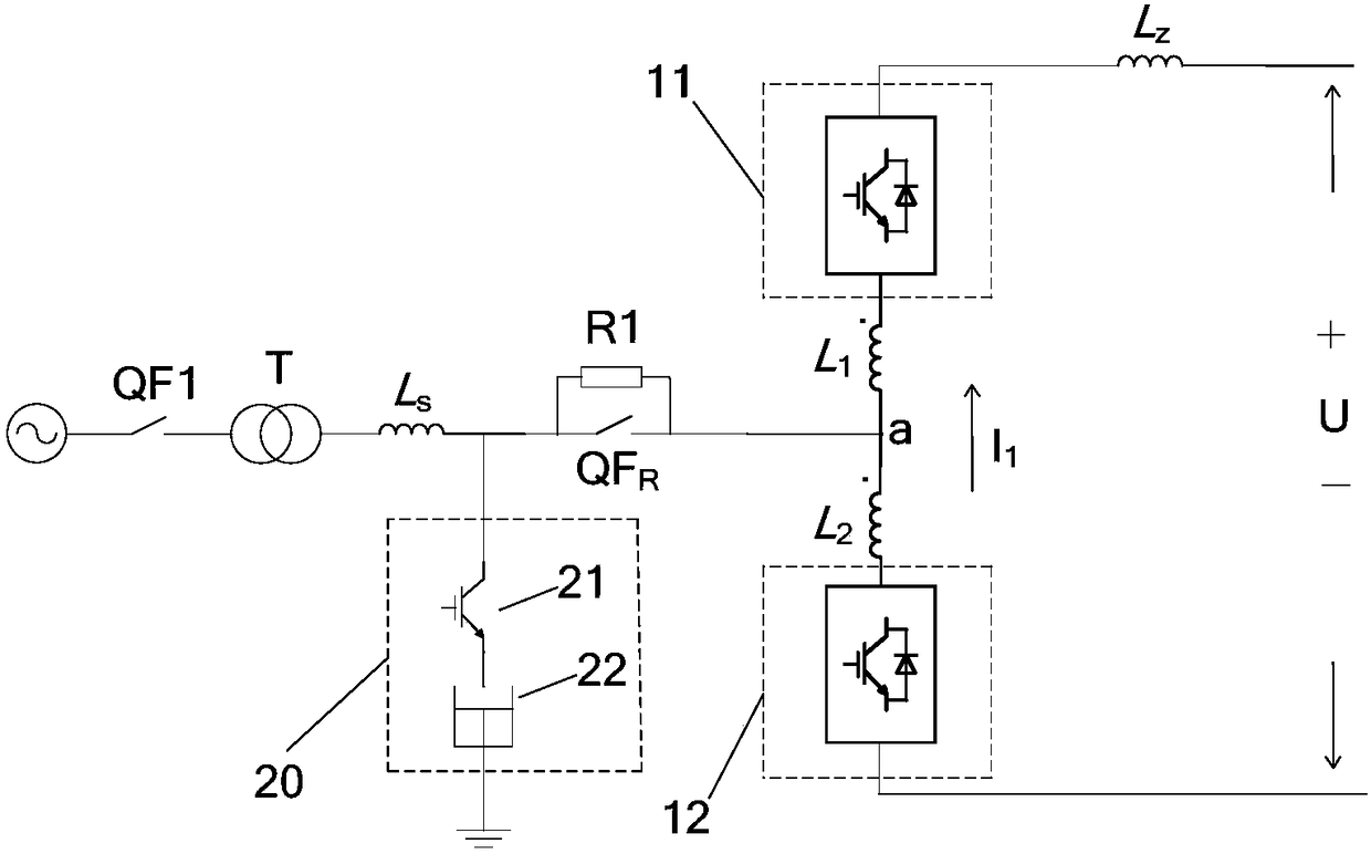
[0019] Such as figure 1 Shown is a schematic structural diagram of a flexible direct current transmission system according to an embodiment of the present invention. The flexible DC transmission system shown in the figure includes a transformer T, a converter and a coupling reactor;

[0020] The coupling reactor includes an upper bridge arm coupling reactor L ...


PUM


Abstract

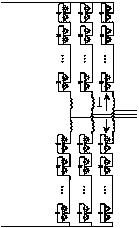
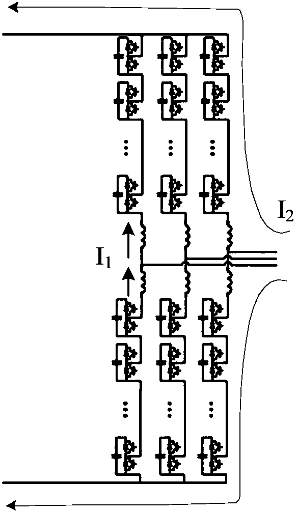
The invention provides a flexible direct current transmission system. The system comprises a transformer, a current converter and a coupling reactor, wherein the coupling reactor comprises an upper bridge arm coupling reactor and a lower bridge arm coupling reactor; the upper bridge arm coupling reactor and the lower bridge arm coupling reactor are connected through a connection of a same-polarityterminal and a different-polarity terminal; a connection point between the same-polarity terminal and the different-polarity terminal is a grid connection point; one end of the transformer is connected with an alternating-current power grid, and the other end is connected with the grid connection point; the current converter comprises three phase units; the phase units include an upper bridge armand a lower bridge arm; and the coupling reactor is connected between the upper bridge arm and the lower bridge arm.

Description

technical field [0001] The invention relates to the field of direct current transmission, in particular to a flexible direct current transmission system. Background technique [0002] With the depletion of fossil energy and the increasing pressure to improve the environment, China and the world are facing a strategic adjustment of energy structure, large-scale development and utilization of new energy is imperative. New energy sources such as wind power, solar energy, and tidal energy are intermittent and random. The large-scale consumption of new energy has become a major practical problem facing China's power system. Traditional power equipment, grid structure, and operation technology have become inadequate. In order to adapt to the profound changes in the future energy pattern, it is necessary to accelerate the research and development of new collection, transmission and consumption technologies to improve the utilization efficiency of new energy power generation. In re...

Claims


Application Information

Patent Timeline
Patent Type & Authority Applications(China)
IPC IPC(8): H02M1/32H02J3/36
CPCH02J3/36H02M1/32Y02E60/60
Inventor 黄天啸辛光明刘苗杜延菱刘蔚王丰吴涛谢欢孟超王沛然张硕高旭马迎新曹天植王炳辉刘蓁
Owner ELECTRIC POWER RES INST STATE GRID JIBEI ELECTRIC POWER COMPANY
Learn More