Heating block with heat dissipation effect

A heat dissipation effect and heating block technology, applied in the direction of ohmic resistance heating, electric heating devices, electrical components, etc., can solve the problems of poor heat dissipation effect, large heating loss, high manufacturing cost, etc., and achieve good heat dissipation effect, small heating loss, and structural simple effect

Inactive Publication Date: 2018-08-14
陈立兵
View PDF0 Cites 0 Cited by
  • Summary
  • Abstract
  • Description
  • Claims
  • Application Information

AI Technical Summary

Problems solved by technology

[0002] The existing electric heater is made of cast copper, which has high heating loss, low efficiency, high manufacturing cost, poor heat dissipation effect and short service life

Method used


Image

  • Heating block with heat dissipation effect

Examples


Embodiment Construction

[0008] The specific content of the present invention will be described in detail below in conjunction with the accompanying drawings and specific embodiments.

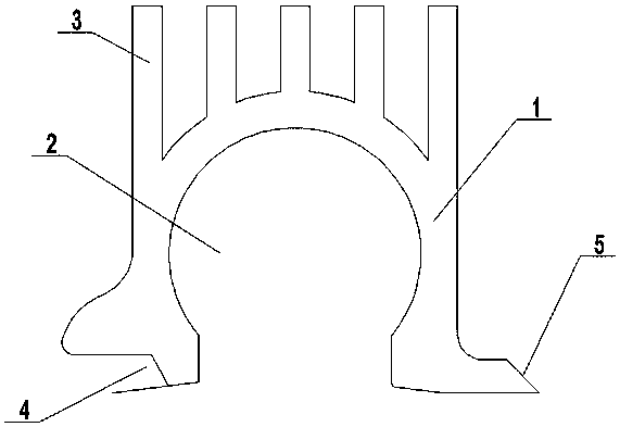
[0009] Such as figure 1 As shown, the heating block with heat dissipation effect includes: a heating block body 1, an installation cavity 2 is arranged in the heating block body 1, a number of cooling fins 3 are uniformly arranged on the upper end of the heating block body 1, and the heating block body 1 The upper end is provided with mutually matching groove 4 and inserting block 5.

[0010] When the heating block with heat dissipation effect mentioned above is used, the heating pipe is installed in the installation cavity 2, and the adjacent heating blocks with heat dissipation effect are connected to each other through the groove 4 and the insert block 5.


PUM


Abstract

The invention discloses a heating block with a heat dissipation effect and convenient to assemble. The heating block comprises a heating block body; a mounting cavity is formed in the heating block body; multiple heat dissipation sheets are uniformly arranged at the upper end of the heating block body; and a groove and an inserting block which are matched mutually are arranged at the upper end ofthe heating block body. The heating block has the advantages of simple structure, convenience in assembling, low heating loss, high efficiency, high heat dissipation effect and long service life.

Description

technical field [0001] The invention relates to an electric heating device, in particular to a heating block with heat dissipation effect. Background technique [0002] The existing electric heater is made of cast copper, which has high heating loss, low efficiency, high manufacturing cost, poor heat dissipation effect and short service life. Contents of the invention [0003] The technical problem to be solved by the present invention is to provide a heating block with convenient assembly and heat dissipation effect. [0004] In order to solve the above technical problems, the technical solution adopted by the present invention is: a heating block with heat dissipation effect, including: a heating block body, an installation cavity is arranged in the heating block body, and a number of cooling blocks are uniformly arranged on the upper end of the heating block body sheet, the upper end of the heating block body is provided with mutually matching grooves and inserting blo...

Claims


Application Information

Patent Timeline
Patent Type & Authority Applications(China)
IPC IPC(8): H05B3/00
CPCH05B3/00
Inventor 陈立兵
Owner 陈立兵
Why Eureka
Try Eureka