A welding machine with a clamping mechanism

A welding machine and clamping plate technology, which is applied in welding equipment, auxiliary welding equipment, welding/cutting auxiliary equipment, etc., can solve the problems that the welded object cannot be clamped and fixed, and the position of the welded object cannot be adjusted.

Active Publication Date: 2020-06-30
淮安溢邦林峰机械制造有限公司
View PDF6 Cites 0 Cited by
  • Summary
  • Abstract
  • Description
  • Claims
  • Application Information

AI Technical Summary

Problems solved by technology

The above-mentioned welding machine welds the LED lamp and the fins together through the welding mechanism to achieve high-efficiency welding operations. However, the existing welding machine cannot firmly clamp and fix the welded object during use, and cannot Adjusting the position of the object to be welded has certain limitations in use

Method used


Image

  • A welding machine with a clamping mechanism
  • A welding machine with a clamping mechanism
  • A welding machine with a clamping mechanism

Examples


Embodiment

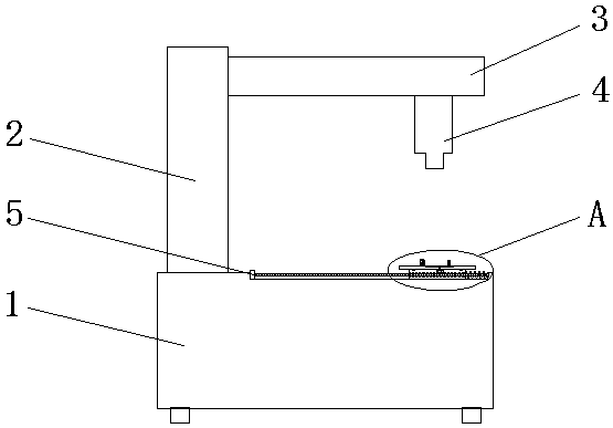
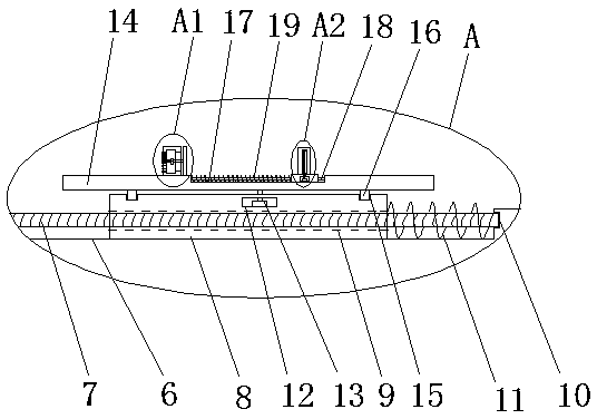
[0023] Example: refer to Figure 1-5 , a welding machine with a clamping mechanism, including an operating table 1, a support rod 2 is fixedly installed on the top side of the operating table 1, a cross-arm rod 3 is fixedly installed on one side of the support rod 2, and a cross-arm rod 3 is fixedly installed on the bottom side of the cross-arm rod 3 The welding head 4 is fixedly installed, and the welding head 4 is located above the operation table 1. The top side of the operation table 1 is provided with a horizontal adjustment mechanism for adjusting the welding position. The horizontal adjustment mechanism includes a first chute opened on the top side of the operation table 1 6. A first rotating motor 5 is fixedly installed on the inner wall of the first chute 6 close to the support rod 2. The output shaft of the first rotating motor 5 is fixedly connected with a first screw 7, and the first screw 7 is far away from the first screw. One end of a rotating motor 5 is rotatab...


PUM


Abstract

The invention discloses a welding machine with a clamping mechanism. The welding machine comprises an operating table, wherein the top side of the operating table is fixedly equipped with a supportingrod; one side of the supporting rod is fixedly equipped with a transverse arm rod; the bottom side of the transverse arm rod is fixedly equipped with a welding head; the welding head is positioned above the operating table; the top side of the operating table is equipped with a horizontal regulating mechanism for regulating a welding position; the horizontal regulating mechanism comprises a firstslide slot formed in the top side of the operating table; and the inner wall of one side, close to the supporting rod, of the first slide slot is fixedly equipped with a first rotary motor. The welding machine can be used for conveniently regulating the position and the angle position, in the horizontal direction, of a rotary table, can be convenient for regulating the height position of a clamped part, is convenient for operation of a small part, can be used for conveniently and stably clamping the object, prevents the object from dropping, has certain buffer force for the clamped object, can prevent the clamped part from being damaged, is convenient for protecting a motor, and prevents the clamping mechanism from being damaged.

Description

technical field [0001] The invention relates to the technical field of welding machines, in particular to a welding machine equipped with a clamping mechanism. Background technique [0002] Many electrical components are manufactured by welding various components together. For example, a wire may be soldered to a conductive trace on a circuit board by a soldering mechanism that bonds the wire to the conductive trace by melting the solder and causing the solder to flow into the junction between the wire and the conductive trace. link. Welding can be done manually or by automated processing. Manual application is time consuming and increases the expense of electrical components. Welding quality is a problem that manual welding has, and automatic processing also has disadvantages. [0003] The patent application number is 201510007865.5 discloses a welding machine, including: a base, a conveying mechanism arranged on the base, a material lifting mechanism, a welding mechani...

Claims


Application Information

Patent Timeline
Patent Type & Authority Patents(China)
IPC IPC(8): B23K37/00B23K37/04
CPCB23K37/00B23K37/006B23K37/0443
Inventor 常俊红
Owner 淮安溢邦林峰机械制造有限公司
Why Eureka
Try Eureka