
A head shrinking machine

A technology of necking and left frame, applied in other home appliances, home appliances, applications, etc., can solve the problems of head shaking, damage, single function, etc., to achieve the effect of easy and stable clamping

Active Publication Date: 2016-09-14
PUYANG CITY HONGYU PRESSURE VESSEL
View PDF12 Cites 0 Cited by
  • Summary
  • Abstract
  • Description
  • Claims
  • Application Information

AI Technical Summary

Problems solved by technology

At present, most of the head shrinking machines are relatively rough in design and manufacture, with single functions, low production efficiency, and poor equipment integration. Most of the fixing of the head during the head shrinking process is through the cooperation of screws and fixtures. Locking, although this method can firmly fix the head, but every time the head is replaced, the bolts must be disassembled and installed, which is inefficient and wastes a lot of manpower and material resources
Moreover, during the sealing process of the existing head shrinking machine, it is easy to cause damage to the end face of the butt end of the head, and in the process of shrinking the head, it is easy to cause the head to shake up and down, which affects the processing accuracy.

Method used


Image

  • A head shrinking machine
  • A head shrinking machine
  • A head shrinking machine

Examples


Embodiment Construction

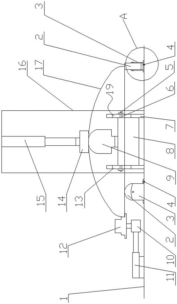
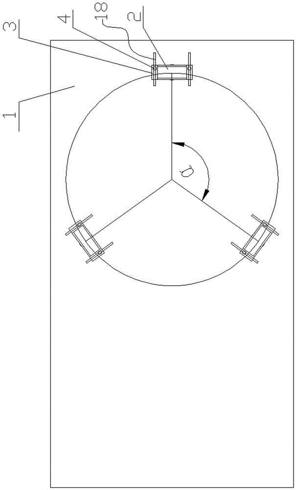
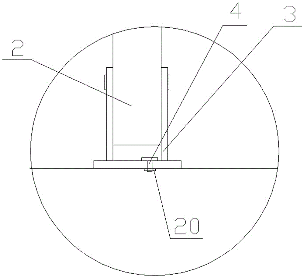
[0015] Such as Figure 1 to Figure 3 As shown, a kind of head shrinking machine of the present invention, it comprises workbench 1, and described workbench 1 is provided with the vertical lower jack column 9 that is axially fixedly connected with motor 8 rotating shaft, vertical lower jack column 9 The upper end of is set as a sphere. Between described motor 8 and workbench 1, be provided with motor elevating frame, described motor elevating frame comprises left frame 13 and right frame 7 that are arranged symmetrically, and described motor 8 is positioned at left frame 13 and right frame 7 In between, symmetrical vertical chute 19 is provided on the opposite sides of left frame 13 and right frame 7, and horizontal bolt 6 is fixedly arranged on the position corresponding to vertical chute 19 on the described motor 8, and horizontal bolt 6 The end of 6 passes through the vertical chute 19, and the transverse bolts 6 are respectively connected with the left frame 13 and the rig...


PUM


Abstract

The invention discloses a necking machine for a seal head. The necking machine comprises a worktable, wherein a vertical lower support pillar which is axially and fixedly connected with a motor rotating shaft is arranged on the worktable; a vertical upper support pillar is arranged at the corresponding position above the vertical lower support pillar; a vertical hydraulic cylinder is arranged at the upper end of the vertical upper support pillar in a connecting manner; a group of supporting wheels are uniformly arranged on the worktable around the vertical lower support pillar; the supporting wheels are positioned on the same circle and top ends of the supporting wheels are positioned in the same plane; a horizontal hydraulic cylinder is also arranged on the worktable; a necking processing roller seat is fixedly arranged at the tail end of a piston rod of the horizontal hydraulic cylinder; a necking processing roller which is connected with the necking processing roller seat in a rotating manner is arranged on the necking processing roller seat. According to the necking machine disclosed by the invention, quick clamping and loosening of the seal head can be realized, the stability and the completeness of the seal head in the processing process are guaranteed, and the processing efficiency and the processing precision of seal head necking are improved; in addition, the necking machine can be suitable for processing seal heads with different heights and different diameters.

Description

technical field [0001] The invention relates to the technical field of head forming, in particular to a head shrinking machine. Background technique [0002] The head is a kind of pressure vessel part, which is usually used at both ends of the tank. The head shrinking machine is used to shrink the butt end of the head and the tank body, so that the diameter of the head interface is smaller than the inner diameter of the tank, and then the butt end of the head can be inserted into the tank body, along the direction of the head alignment stage. The side wall is welded to the tank body, which enhances the sealing and stability of the interface. At present, most of the head shrinking machines are relatively rough in design and manufacture, with single functions, low production efficiency, and poor equipment integration. Most of the fixing of the head during the head shrinking process is through the cooperation of screws and fixtures. Locking, although this method can fix the h...

Claims


Application Information

Patent Timeline
Patent Type & Authority Patents(China)
IPC IPC(8): B21D51/44B21D19/00
Inventor 万红涛陈国芳万红彬
Owner PUYANG CITY HONGYU PRESSURE VESSEL
Learn More