Mold assembly for steel disc injection molding in mold

An in-mold injection and steel sheet technology, applied in the direction of coating, etc., can solve problems such as mold damage, scratches between steel sheets and molds, and deviations

Inactive Publication Date: 2018-08-17
YULONG COMPUTER TELECOMM SCI (SHENZHEN) CO LTD
View PDF3 Cites 1 Cited by
  • Summary
  • Abstract
  • Description
  • Claims
  • Application Information

AI Technical Summary

Problems solved by technology

[0004] For this reason, the technical problem to be solved by the present invention is that the steel sheet in the injection mold in the prior art may be deviated due to the existence of the gap when it is placed, which

Method used


Image

  • Mold assembly for steel disc injection molding in mold
  • Mold assembly for steel disc injection molding in mold
  • Mold assembly for steel disc injection molding in mold

Examples


Embodiment Construction

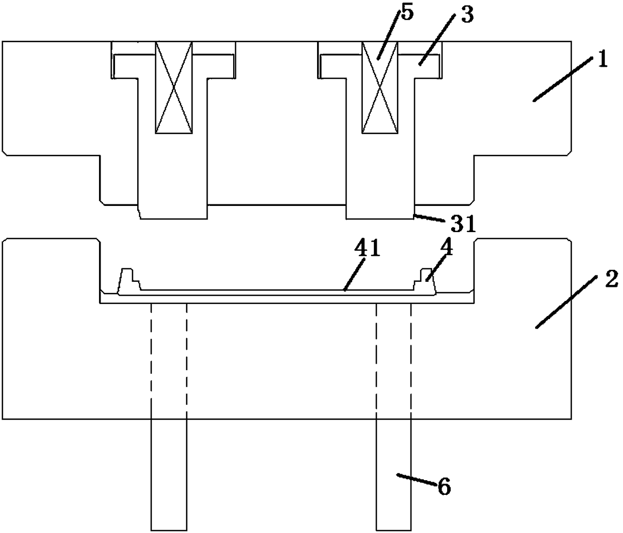
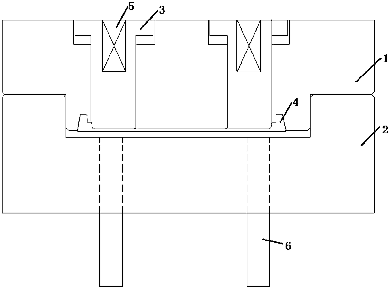
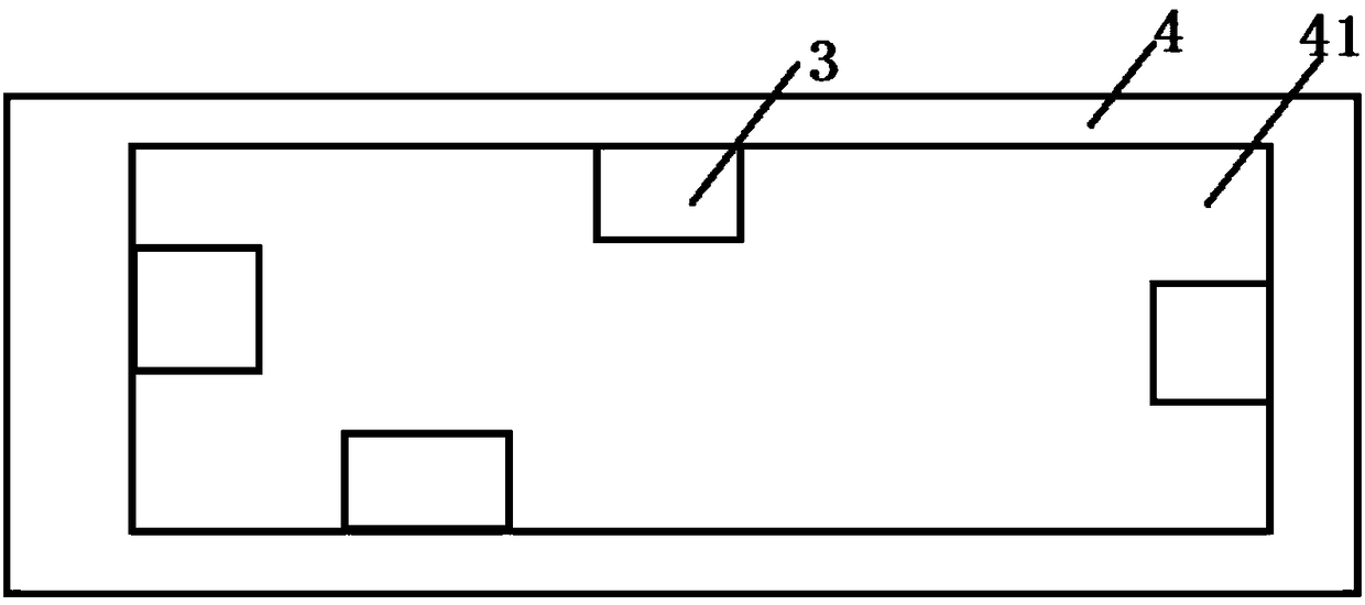
[0019] A mold assembly for in-mold injection molding of steel sheets, comprising a punch 1 and a die 2 adapted to the punch 1, the punch 1 in this embodiment is a front mold core, and the die 2 is the rear die core, and the male die 1 is arranged above the female die 2 . Of course, the positions of the male die 1 and the female die 2 can also be reversed, that is, the female die 2 is arranged above. An injection-molded steel sheet 4 is arranged in the die 2, and a square cavity 41 is formed on the injection-molded steel sheet 4. A plurality of square inserts 3 are arranged on the punch 1, and the square inserts 3 face toward the The concave mold 2 extends out from the punch 1, and the square inserts 3 have at least four sides in the square inserts 3 before the punch 1 and the concave mold 2 are closed. The four side walls of the concave cavity 41 are against each other. In this embodiment, the respective two sides of the two square inserts 3 are respectively against the four ...


PUM


Abstract

The invention relates to an injection mold, in particular to a mold assembly for steel disc injection molding in a mold. The mold assembly comprises a male mold and a female mold matched with the malemold. The male mold is a front mold core, the female mold is a rear mold core, and the male mold is arranged above the female mold. The mold assembly for steel disc injection molding in the mold is higher in centering precision and is provided to solve the technical problems that according to an injection mold in the prior art, when a steel disc is put, deviation probably exists due to gaps, thesteel disc is prone to being seriously scratched with the mold, and even the mold is damaged after long-time using.

Description

technical field [0001] The invention relates to an injection mold. In particular, it relates to a mold assembly for in-mold injection molding of steel sheets. Background technique [0002] With the development of communication technology, users have higher and higher requirements for the thin and light design of the mobile phone body. Therefore, in-mold injection-molded steel sheets are commonly used in the manufacture of mobile phone bodies. [0003] Chinese patent CN206335807U discloses a positioning structure for an injection mold and an injection molded steel sheet in the mold, that is, in the prior art, the steel sheet is placed on the positioning column by punching holes on the steel sheet and setting a positioning column outside the molding cavity Perform mold closing. However, in order to avoid interference between each positioning column and the positioning hole due to machining errors, the size of the positioning hole is often slightly larger. That is to say, t...

Claims


Application Information

Patent Timeline
IPC IPC(8): B29C45/14
Inventor 李腾飞
Owner YULONG COMPUTER TELECOMM SCI (SHENZHEN) CO LTD
Why Eureka
Try Eureka