Method for detecting water flow rate and water temperature and water flow rate sensor

A water flow sensor, water temperature detection technology, applied in the direction of measuring flow/mass flow, liquid/fluid solids measurement, instruments, etc., can solve the problem of inability to ensure the absolute installation position and angle of the sensor, the valve body is frozen, the structure is complex, etc. Achieve the effect of preventing icing, stable distance control and high detection accuracy

Pending Publication Date: 2018-08-17
GUANGDONG MACRO GAS APPLIANCE
View PDF16 Cites 3 Cited by
  • Summary
  • Abstract
  • Description
  • Claims
  • Application Information

AI Technical Summary

Problems solved by technology

One of the Chinese invention patents with the patent number CN107131653A discloses the control device of the gas water heater, the gas water heater and its water flow calculation method. It includes ultrasonic sensors installed on both sides of the valve body, and the included angle with the pipe wall is 45 degrees. , but in the actual production, processing and assembly, the absolute installation position and angle of the sensor cannot be guaranteed, and there is a large error
In addition, the valve body of the water flow sensor is now gradually using plastic parts to replace copper parts. When the ambient temperature is low, there are many situations where the valve body freezes and cracks. At present, there are related structures or patents that can automatically drain and prevent freezing, but their structures are complicated and have not been realized. to promote

Method used


Image

  • Method for detecting water flow rate and water temperature and water flow rate sensor
  • Method for detecting water flow rate and water temperature and water flow rate sensor
  • Method for detecting water flow rate and water temperature and water flow rate sensor

Examples


Embodiment Construction

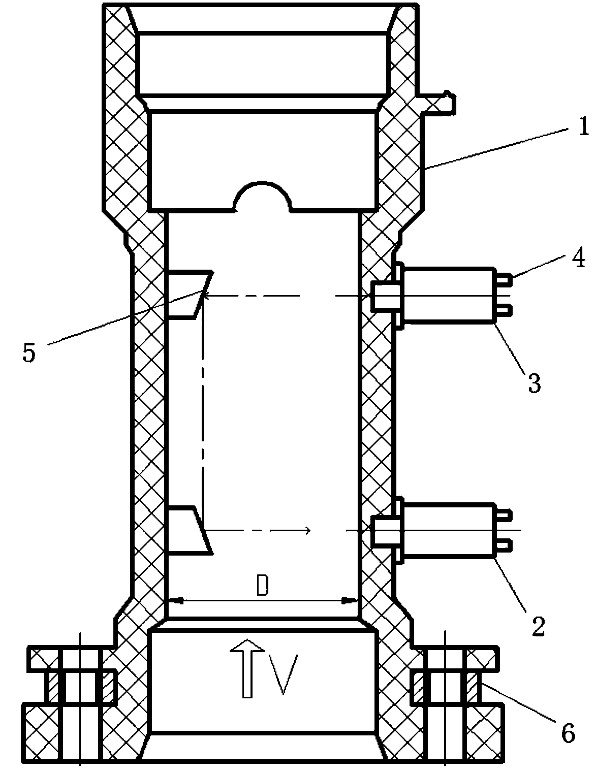
[0033] In the description of the present invention, it should be noted that for orientation words, such as the term "center", "horizontal", "longitudinal", "length", "width", "thickness", "upper", "lower" , "Front", "Back", "Left", "Right", "Vertical", "Horizontal", "Top", "Bottom", "Inner", "Outer", "Clockwise", "Counterclockwise " and other indication orientations and positional relationships are based on the orientations or positional relationships shown in the drawings, and are only for the convenience of describing the present invention and simplifying the description, rather than indicating or implying that the device or element referred to must have a specific orientation, or in a specific orientation. The structure and operation should not be construed as limiting the specific protection scope of the present invention.

[0034] In addition, terms such as "first" and "second" are used for descriptive purposes only, and cannot be understood as indicating or implying rela...


PUM


Abstract

The invention discloses a method for detecting the water flow rate and water temperature. By arranging two ultrasonic receiving and transmission devices, according to the time difference and transmission distance of signals received by the ultrasonic receiving and transmission devices and the diameter of a pipe body, the water flow rate of a water flow rate sensor is precisely calculated in real time, and the influence of water temperature change on detection of the water flow rate is completely removed. In addition, according to the time difference, the transmission distance and the diameterof the pipe body, the ultrasonic transmission speed at the current water temperature can be calculated, then the current water temperature is inversely deduced according to the ultrasonic transmissionspeed, and the aim of detecting the water temperature without a temperature sensor is achieved. According to the water flow rate sensor, a pair of ultrasonic receiving and transmission devices are arranged at the same side of the pipe body, the distance between the ultrasonic receiving and transmission devices is stably controlled, the situation is avoided that other non-mechanical water flow rate sensors are greatly influenced by factors such as corner installation and included angle precision of the sensors, and the detection precision is higher.

Description

technical field [0001] The invention relates to the technical field of water heaters, in particular to a method for detecting water flow and water temperature of a water heater and a water flow sensor. Background technique [0002] At present, water heaters have been widely used in ordinary households. During use, in order to ensure the user's bathing comfort, it is necessary to ensure that the outlet water temperature of the water heater is stable in real time. Usually, the outlet water temperature is controlled by the main controller of the water heater according to the water flow and water temperature in the water inlet pipe to control the supply of gas, that is, it is controlled by Q=cmΔT, where c is the specific heat capacity of water, m is the water quality, and ΔT is the temperature rise . [0003] Most of the main controllers of existing gas water heaters obtain water flow through mechanical water flow sensors, which are mainly composed of valve body, water flow ro...

Claims


Application Information

Patent Timeline
Patent Type & Authority Applications(China)
IPC IPC(8): G01F1/66G01D21/02
CPCG01D21/02G01F1/662
Inventor 艾穗江刘兵阳悠悠
Owner GUANGDONG MACRO GAS APPLIANCE
Why Eureka
Try Eureka