3D InISAR imaging method of ship target in sparse aperture

A technology of sparse aperture and imaging method, applied in the direction of radio wave reflection/re-radiation, using re-radiation, measuring devices, etc., can solve the problem of low precision and achieve the effect of improving the accuracy of coordinate reconstruction

Active Publication Date: 2018-08-17
HARBIN INST OF TECH
View PDF5 Cites 19 Cited by
  • Summary
  • Abstract
  • Description
  • Claims
  • Application Information

AI Technical Summary

Problems solved by technology

[0004] The purpose of the present invention is to solve the problem that the accuracy of three-dimensional geometric reconstruction of each scattering point on the ship target is low when the radar receiving echo is incomplete, and proposes a three-dimensional InISAR imaging method for ship target under sparse aperture

Method used


Image

  • 3D InISAR imaging method of ship target in sparse aperture
  • 3D InISAR imaging method of ship target in sparse aperture
  • 3D InISAR imaging method of ship target in sparse aperture

Examples


specific Embodiment approach 1

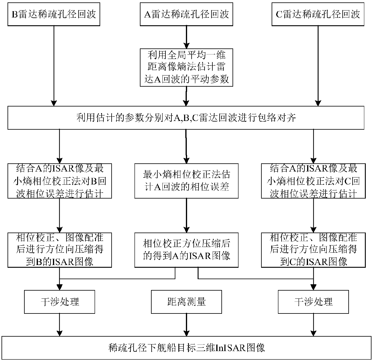
[0014] Specific implementation mode one: combine figure 1 To illustrate this embodiment, the specific process of a three-dimensional InISAR imaging method for a ship target with a sparse aperture in this embodiment is as follows:

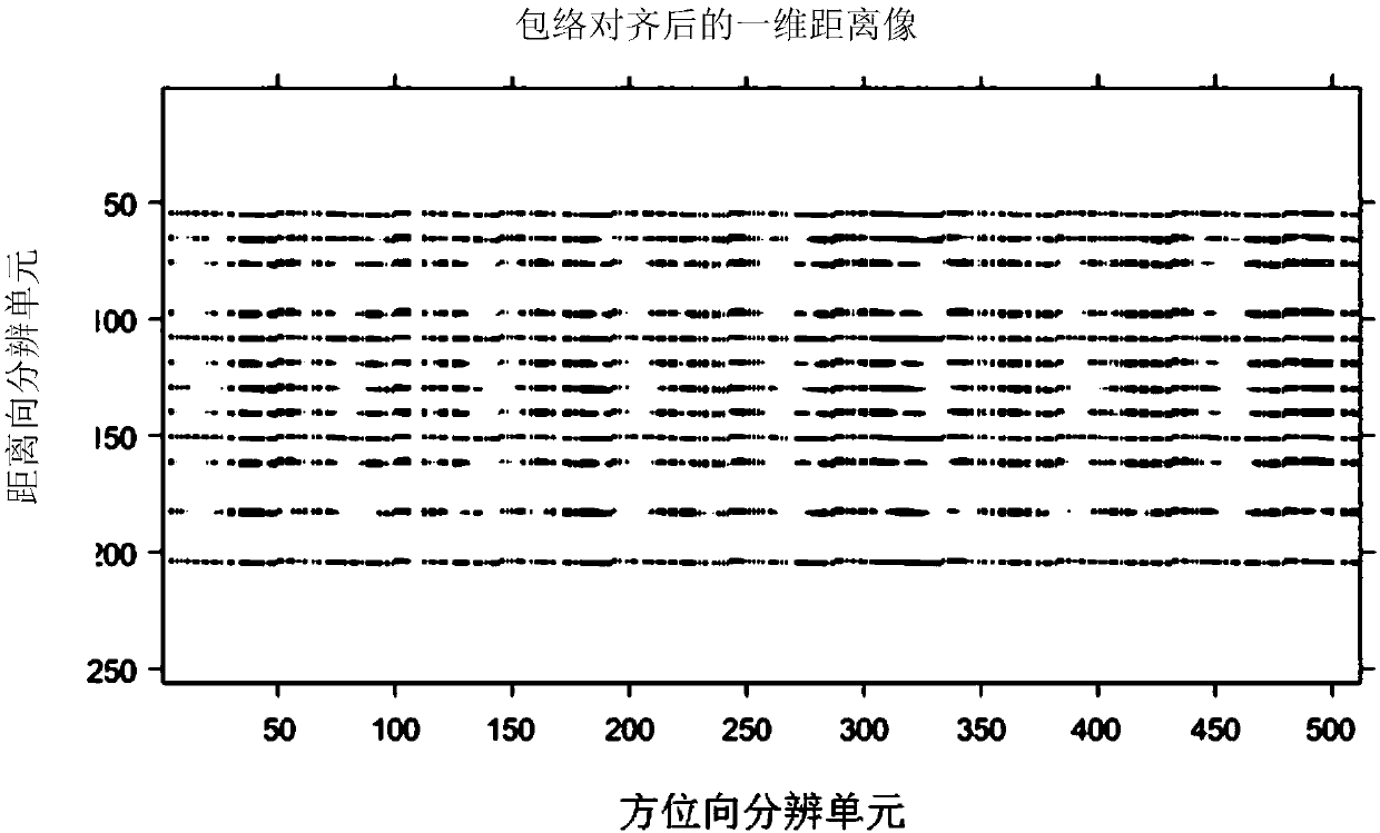
[0015] Radars A, B, and C respectively receive sparse aperture echoes. First, the global average one-dimensional range image entropy minimization algorithm is used to estimate the target’s translational parameters for the echoes of radar A, and the optimal estimation of the translational parameters is obtained through step-by-step iterations. value; in order to make each scattering point of the target focus on the same range unit in the three ISAR images obtained by radars A, B, and C, the optimal translation parameters estimated by radar A are compared to radars A, B, and C respectively. The received sparse aperture echoes are compensated to achieve envelope alignment, and the compensated echoes are compressed in the range direction to obtain a on...

specific Embodiment approach 2

[0018] Specific embodiment 2: the difference between this embodiment and specific embodiment 1 is: in said step 2, the method with the smallest global average one-dimensional distance image entropy is adopted for S A The translation component of (m,n) is estimated to obtain the optimal estimate Δr of the translation component; the specific process is:

[0019] Step 21. Given the initial distance vector Δr=0, calculate the global average one-dimensional range image of radar A

[0020] Step 22, calculate the Shannon entropy as

[0021] Step two and three, estimate Δr:

[0022] Δr(m)=max r=1,1,…,N IFFT((FFT(f A (m,r))) * FFT(ln(f Aave (-r))));

[0023] m=1,2,...,M; (·) * To take the conjugate, FFT is Fourier transform, IFFT Fourier inverse transform;

[0024] Step 24: Update the average one-dimensional distance image Calculate the Shannon entropy E again;

[0025] Step 25: Determine whether the entropy E has decreased, and if so, return to Step 2 and 3 to continu...

specific Embodiment approach 3

[0027] Specific embodiment three: the difference between this embodiment and specific embodiment one or two is that the Δr obtained in the step three is used to compensate the echoes of the radars A, B, and C respectively, and the distance of the compensated echoes is calculated. The one-dimensional range image after being compensated for compression; the specific process is:

[0028] In order to ensure accurate interference in 3D imaging, it is necessary to use the translational parameters of radar A to compensate for each radar echo, as follows:

[0029] S A1 (m,n)=S A (m,n)exp(-j2πnΔr(m) / N) (1)

[0030] S B1 (m,n)=S B (m,n)exp(-j2πnΔr(m) / N) (2)

[0031]

[0032] In the formula j is a unit imaginary number; S A1 (m,n) is the echo of radar A after compensation, S B1 (m,n) is the echo of radar B after compensation, S C1 (m,n) is the echo after compensation for radar C; respectively for S A1 (m,n), S B1 (m,n), S C1 (m,n) is compressed in the distance dimension, ...


PUM


Abstract

The invention relates to an InISAR imaging method of a ship target in the sparse aperture under the condition of echo loss, and aims at solving the problem that 3D geometric reconstruction of scatterings in the ship target is low in precision when echoes received by a radar are incomplete. The method comprises that 1) it is supposed that radars A, B and C receive sparse aperture echoes of the target; 2) an optimal value of a translation component is estimated, and the echoes are compensated; 3) a one-dimensional distance image after translation compensation is obtained; 4) a phase error and awave path different are estimated, and the one-dimensional distance image is compensated via estimated values; 5) ISAR images of the radars A, B and C are obtained via azimuth compression; and 6) interference processing is carried out on each ISAR image of the radars A, B and C along two baselines, and a 3D InISAR reconstruction image of the ship target in the sparse aperture is realized by combining range finding information. The method can be used for the technical field of radars.

Description

technical field [0001] The invention relates to a three-dimensional InISAR imaging method of a ship target under the condition of echo loss (sparse). Background technique [0002] The 3D InISAR imaging technology has achieved rapid development because it can directly obtain the 3D coordinate reconstruction of the target, but the existing algorithms are mainly for the echo in the full aperture. However, in actual radar work, due to the unknown environment and the characteristics of time-sharing work of multi-function radars, there will be random absence of radar receiving echoes and sub-aperture receiving states, making the original 3D InISAR imaging for complete aperture signals method will no longer apply. At present, the three-dimensional imaging method that better solves the problem of receiving less or missing echo data is mainly to use compressed sensing to restore the missing data and then use traditional algorithms to achieve it. Although these methods can obtain be...

Claims


Application Information

Patent Timeline
Patent Type & Authority Applications(China)
IPC IPC(8): G01S13/90
CPCG01S13/90G01S13/9023G01S13/9064
Inventor 王勇陈雪飞
Owner HARBIN INST OF TECH
Why Eureka
Try Eureka