Structured light projection module, camera component, and electronic apparatus

A camera component and structured light technology, applied in the field of three-dimensional imaging, can solve the problems of laser energy attenuation, laser pattern affecting the accuracy of depth image acquisition, etc., and achieve the effect of improving brightness uniformity

Active Publication Date: 2018-08-17
GUANGDONG OPPO MOBILE TELECOMM CORP LTD
View PDF5 Cites 4 Cited by
  • Summary
  • Abstract
  • Description
  • Claims
  • Application Information

AI Technical Summary

Problems solved by technology

The reason for this phenomenon is that the laser light away from the optical axis of the structured light projection module has to go through a longer optical path to reach the plane, so the energy of the laser light is attenuated more
The unevenness of the overall brightness of the laser pattern will affect the acquisition accuracy of the depth image

Method used


Image

  • Structured light projection module, camera component, and electronic apparatus
  • Structured light projection module, camera component, and electronic apparatus
  • Structured light projection module, camera component, and electronic apparatus

Examples


Embodiment Construction

[0017] Embodiments of the present invention are described in detail below, examples of which are shown in the drawings, wherein the same or similar reference numerals designate the same or similar elements or elements having the same or similar functions throughout. The embodiments described below by referring to the figures are exemplary and are intended to explain the present invention and should not be construed as limiting the present invention.

[0018] In the description of the present invention, it should be understood that the terms "first" and "second" are used for description purposes only, and cannot be interpreted as indicating or implying relative importance or implicitly indicating the quantity of indicated technical features. Thus, a feature defined as "first" or "second" may explicitly or implicitly include one or more of said features. In the description of the present invention, "plurality" means two or more, unless otherwise specifically defined.

[0019] I...


PUM


Abstract

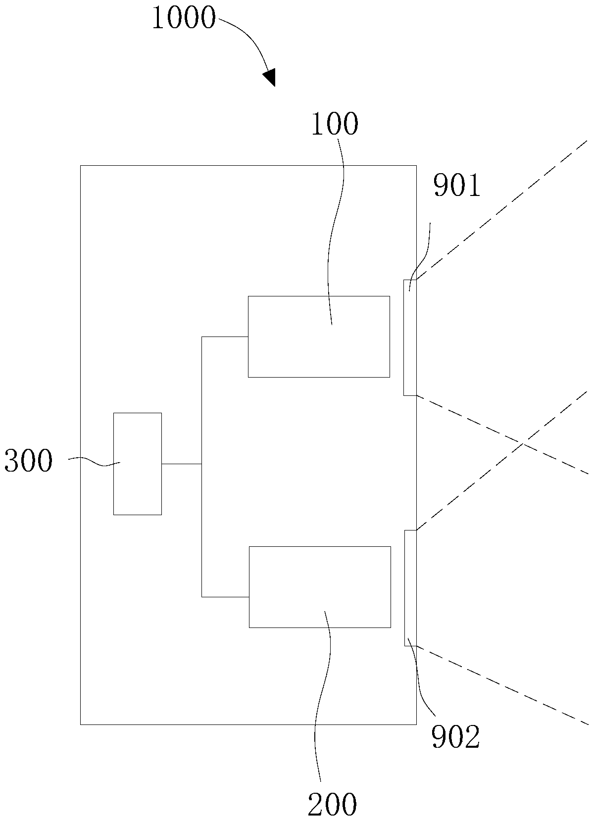
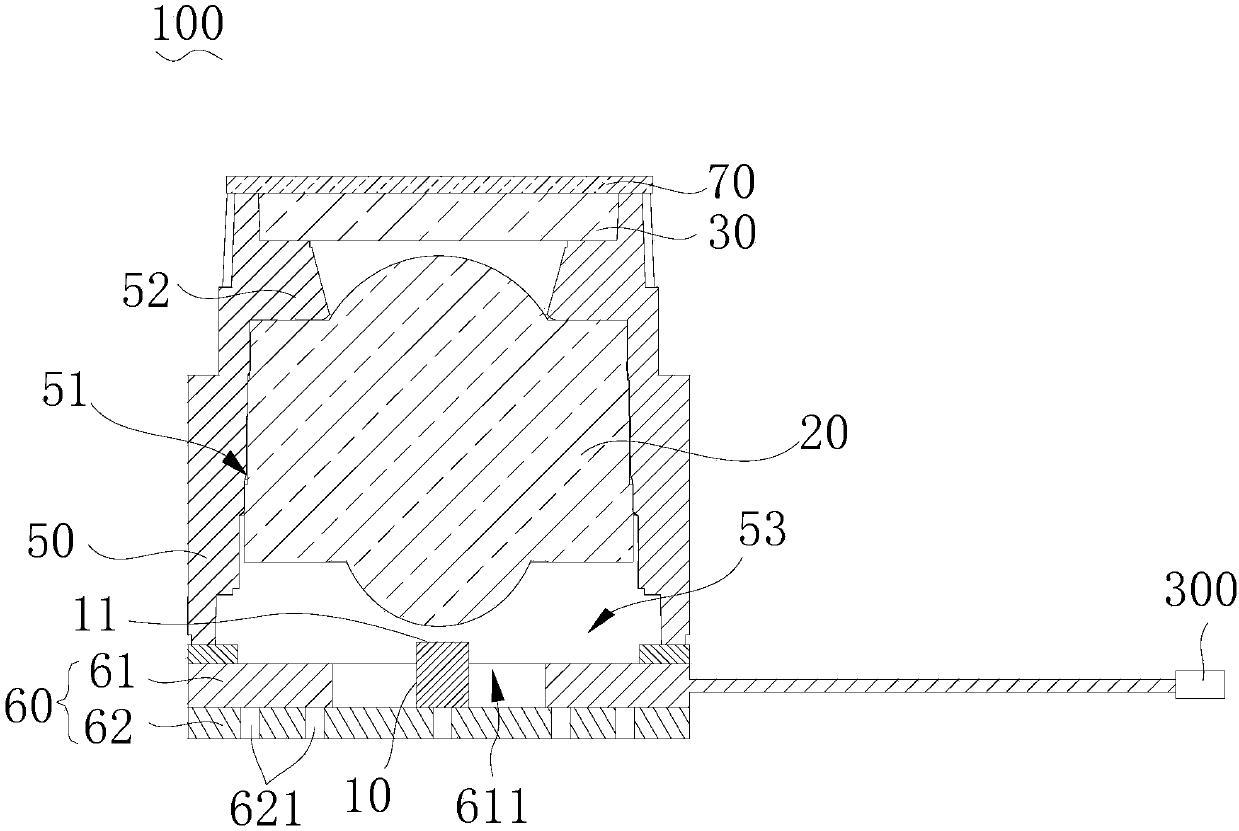
The invention discloses a structured light projection module, a camera component, and an electronic apparatus. The structured light projection module comprises a light source, a collimation element and a diffraction component, the light source is used for emitting laser, the collimation element is used for collimating laser emitted by the light source, the light source comprises an edge-emitting laser, the edge-emitting laser comprises a light emitting surface, the light emitting surface is arranged towards the collimation element, the diffraction component comprises a diffraction grating anda diffusion lens, and the diffraction component is used for diffracting the laser collimated by the collimation element and diffusing the laser to compensate the intensity of the laser with an angulardisplacement relative to the optical axis of the collimation element. According to the structured light projection module, the camera component, and the electronic apparatus, through the setting of the diffraction component comprising the diffusion lens, the intensity of the laser with the angular displacement relative to the optical axis of the collimation element is compensated by employing thediffusion lens, and the brightness uniformity of emitted laser patterns is improved.

Description

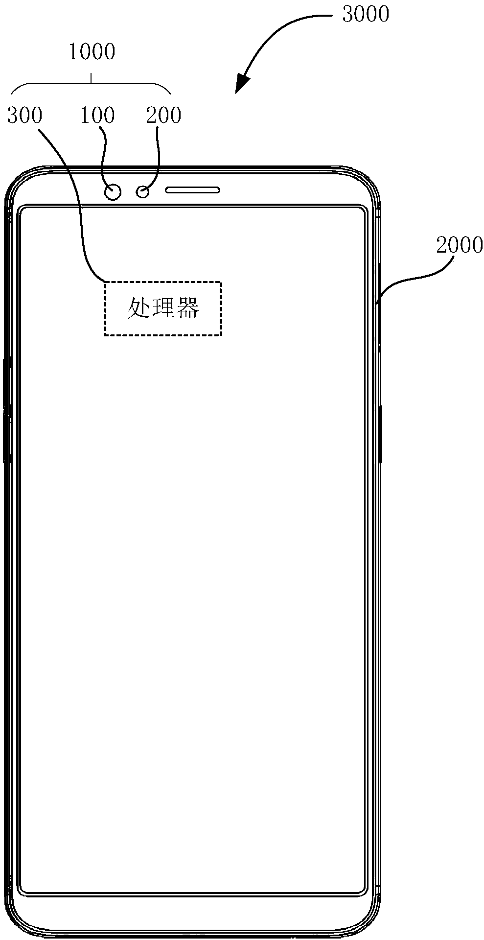
technical field [0001] The invention relates to the technical field of three-dimensional imaging, in particular to a structured light projection module, a camera component and an electronic device. Background technique [0002] When the existing structured light projection module projects the laser pattern onto a plane perpendicular to the optical axis of the structured light projection module in the target space, the brightness of the laser pattern near the optical axis of the structured light projection module is usually brighter. Along the direction away from the optical axis of the structured light projection module, the brightness of the laser pattern decreases gradually. The reason for this phenomenon is that the laser light away from the optical axis of the structured light projection module has to go through a longer optical path to reach the plane, so the energy of the laser light is attenuated more. The unevenness of the overall brightness of the laser pattern wil...

Claims


Application Information

Patent Timeline
IPC IPC(8): G03B15/02G02B27/42H04N13/204
CPCG02B27/4272G03B15/02
Inventor 张学勇
Owner GUANGDONG OPPO MOBILE TELECOMM CORP LTD
Why Eureka
Try Eureka