
Method and system for suppressing circulating current when virtual synchronous machine is connected to grid

A technology of virtual synchronous machine and circulation suppression, which is applied in the direction of single-network parallel feeding arrangement, AC network circuit, electrical components, etc., to achieve consistent outlet voltage, suppression of circulation, and consistent line voltage drop

Active Publication Date: 2021-06-25
ELECTRIC POWER RES INST OF GUANGDONG POWER GRID
View PDF5 Cites 0 Cited by
  • Summary
  • Abstract
  • Description
  • Claims
  • Application Information

AI Technical Summary

Problems solved by technology

[0015] The present invention provides a method and system for suppressing the circulating current when the virtual synchronous machine is connected to the grid, so as to solve the problem of how to suppress the circulating current when the virtual synchronous machine is connected to the grid

Method used


Image

  • Method and system for suppressing circulating current when virtual synchronous machine is connected to grid
  • Method and system for suppressing circulating current when virtual synchronous machine is connected to grid
  • Method and system for suppressing circulating current when virtual synchronous machine is connected to grid

Examples


Embodiment Construction

[0055] Exemplary embodiments of the present invention will now be described with reference to the drawings; however, the present invention may be embodied in many different forms and are not limited to the embodiments described herein, which are provided for the purpose of exhaustively and completely disclosing the present invention. invention and fully convey the scope of the invention to those skilled in the art. The terms used in the exemplary embodiments shown in the drawings do not limit the present invention. In the figures, the same units / elements are given the same reference numerals.

[0056]Unless otherwise specified, the terms (including scientific and technical terms) used herein have the commonly understood meanings to those skilled in the art. In addition, it can be understood that terms defined by commonly used dictionaries should be understood to have consistent meanings in the context of their related fields, and should not be understood as idealized or overl...


PUM


Abstract

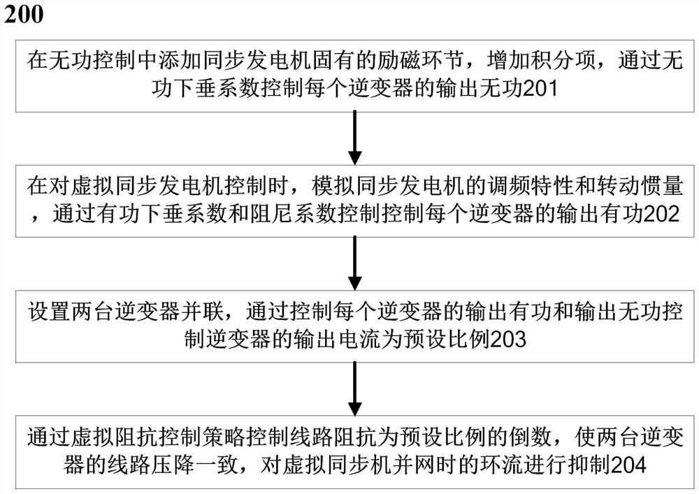
The invention discloses a method for suppressing the circulating current when a virtual synchronous machine is connected to the grid, which is characterized in that a dual-machine parallel mode is set, and a virtual impedance is introduced into the double closed-loop control of the inverter to suppress the circulating current, which specifically includes: In the reactive power control, the inherent excitation link of the synchronous generator is added, the integral term is added, and the output reactive power of each inverter is controlled by the reactive power droop coefficient; when controlling the virtual synchronous generator, the frequency modulation characteristics and Moment of inertia, control the output active power of each inverter through the active power droop coefficient and damping coefficient; set two inverters in parallel, and control the output current of the inverter by controlling the output active power and output reactive power of each inverter is the preset ratio; the line impedance is controlled to be the reciprocal of the preset ratio through the virtual impedance control strategy, so that the line voltage drops of the two inverters are consistent, and the circulating current when the virtual synchronous machine is connected to the grid is suppressed.

Description

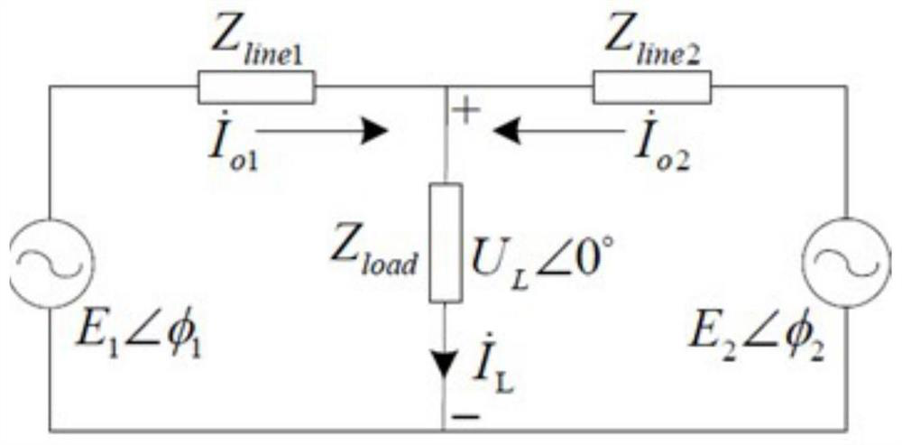
technical field [0001] The present invention relates to the field of metering and calibration, and more specifically, relates to a method and system for suppressing circulation when a virtual synchronous machine is grid-connected. Background technique [0002] When connected to the grid, the output power (current) of the inverter is controllable, so the so-called circulating current is mainly reflected in the island operation of the inverter. The island operation mode of parallel inverters is as follows: figure 1 shown. The output current of the inverter is divided into two parts, one is the load current, and the other is the circulating current between the inverters. It can be seen from the circulating current component that when the output voltage amplitude and phase of the two inverters are the same, the circulating current component is 0. Circulation Influencing Factors: [0003] The output power of the i-th inverter is: [0004] [0005] [0006] Since the co...

Claims


Application Information

Patent Timeline
Patent Type & Authority Patents(China)
IPC IPC(8): H02J3/38H02J3/48H02J3/50
CPCH02J3/381H02J3/48H02J3/50H02J3/388H02J2203/20
Inventor 唐酿盛超陈晓科黄辉黄明欣陈迅赵兵
Owner ELECTRIC POWER RES INST OF GUANGDONG POWER GRID
Learn More