
Automatic oil coating device of automobile motor rotor

A technology for motor rotors and oiling devices, which is applied in the direction of electromechanical devices, devices for coating liquid on the surface, electric components, etc., can solve the problems of low efficiency, achieve the effects of increasing speed, good dust removal, and low efficiency

Active Publication Date: 2018-08-17
安徽航嘉汽车零部件制造有限公司
View PDF6 Cites 6 Cited by
  • Summary
  • Abstract
  • Description
  • Claims
  • Application Information

AI Technical Summary

Problems solved by technology

[0004] The purpose of the present invention is to provide an automatic oiling device for motor rotors of automobiles, so as to solve the problem of low efficiency in the prior art of manual oiling and antirust treatment of motor rotors

Method used


Image

  • Automatic oil coating device of automobile motor rotor
  • Automatic oil coating device of automobile motor rotor
  • Automatic oil coating device of automobile motor rotor

Examples


Embodiment Construction

[0028] The following is further described in detail through specific implementation methods:

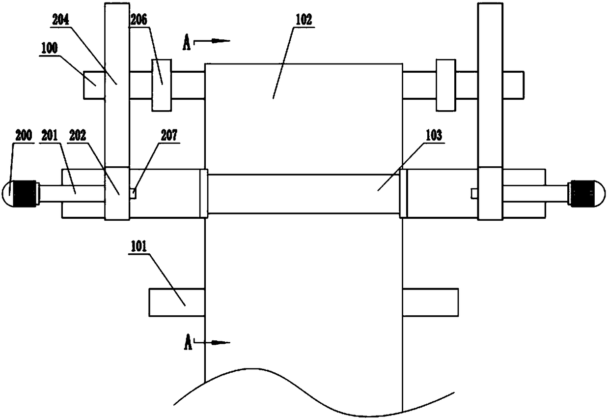
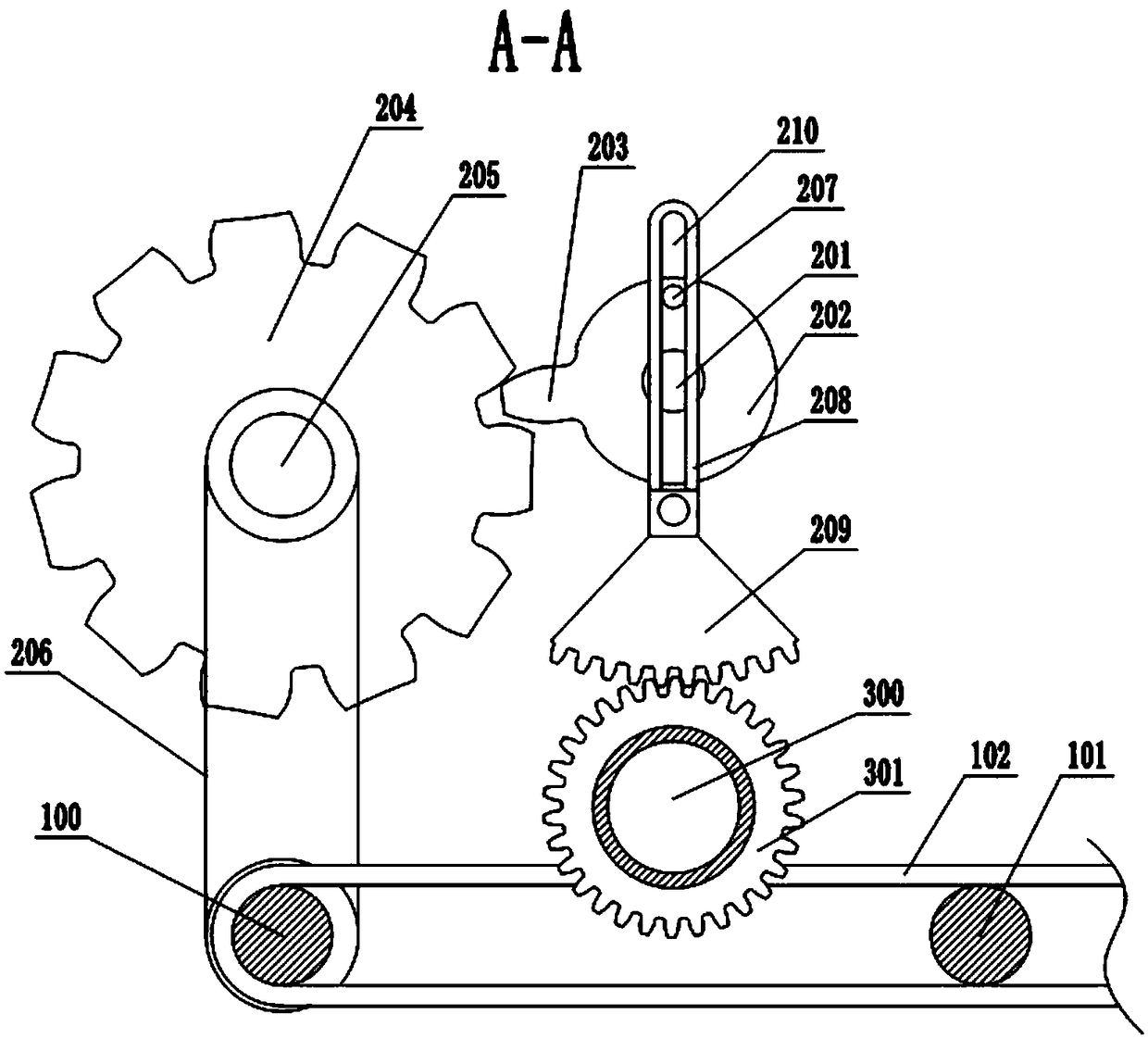
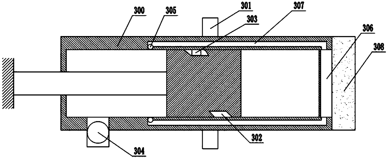
[0029] The reference signs in the drawings of the description include: tensioning shaft 100, support shaft 101, conveyor belt 102, positioning slot 103, motor 200, rotating shaft 201, driving wheel 202, convex teeth 203, first gear 204, gear shaft 205, belt Transmission mechanism 206, first bump 207, swing arm 208, sector gear 209, first groove 210, cylinder 300, second gear 301, second groove 302, second bump 303, oil inlet valve 304, outlet Oil valve 305, oil tank 306, oil pipe 307, sponge 308, air intake check valve 309, air outlet check valve 310, air spray head 311.

[0030] Such as figure 1 and figure 2 Shown is the embodiment of the present invention, announced the automatic oiling device of automobile motor rotor, and this device is made up of three parts, comprises the transfer device that transports the motor rotor to be oiled, drives the drive device that transfers devi...


PUM


Abstract

The invention discloses an automatic oil coating device of an automobile motor rotor. A transfer device comprises a conveying belt on a tension shaft and a support shaft, a driving device comprises arotation shaft, a driving wheel is fixedly arranged at an end part of the rotation shaft and is provided with convex teeth, the driving wheel is engaged with a first gear, a first convex block is concentrically arranged at an end surface of the driving wheel, the driving device also comprises a swinging piece, the swinging piece comprises a swinging arm and a fan-shaped gear, a brushing device comprises an air cylinder, the air cylinder is arranged below the swinging piece, an oil inlet valve and an oil outlet valve are arranged on a side wall of the air cylinder at one side of an air cylinderpiston rod, an oil groove is formed in the bottom of the air cylinder, the brushing device covers the oil groove, an oil pipe is arranged in the side wall of the air cylinder between the oil outlet valve and the oil groove, an air inlet one-way valve and an air outlet one-way valve are arranged on the side wall of the air cylinder at one side far away from the air cylinder piston rod, and an airspraying head is arranged on a side wall of the brushing device. With the adoption of the automatic oil coating device disclosed by the technical scheme, automatic oil removal and rust prevention areperformed on the motor rotor, and the efficiency is greatly improved.

Description

technical field [0001] The invention relates to the technical field of motor rotor processing, in particular to an automatic oiling device for an automobile motor rotor. Background technique [0002] The motor is a device that can convert electrical energy into mechanical energy. It is the most commonly used electric machine and plays an extremely important role in our social production and life. The structure of the motor is mainly composed of a stator, a rotor and an end cover. Among them, in order to prevent the rust on the end face of the rotor from affecting the working life of the motor, it is necessary to apply a layer of anti-rust oil on the two end faces of the motor rotor when manufacturing the motor rotor. Now, when the general enterprise applies anti-rust oil to the motor rotor, it mainly uses artificial methods. Apply by way, that is, use a brush-like tool to dip in the anti-rust oil, and then apply it on the end face of the motor rotor. [0003] First of all, ...

Claims


Application Information

Patent Timeline
Patent Type & Authority Applications(China)
IPC IPC(8): H02K15/02H02K15/12B05C1/06B05C13/02B05C11/10
CPCB05C1/06B05C11/10B05C13/02H02K15/02H02K15/12
Inventor 罗勇
Owner 安徽航嘉汽车零部件制造有限公司
Learn More