
Time division multiplexing piezoelectric circuit and control method thereof, and piezoelectric apparatus

A time-division multiplexing, piezoelectric device technology, applied in the direction of piezoelectric effect/electrostrictive or magnetostrictive motors, measurement of properties using piezoelectric devices, generators/motors, etc. low level issues

Active Publication Date: 2018-08-17
BOE TECH GRP CO LTD
View PDF4 Cites 7 Cited by
  • Summary
  • Abstract
  • Description
  • Claims
  • Application Information

AI Technical Summary

Problems solved by technology

[0005] Embodiments of the present invention provide a time-division multiplexing piezoelectric circuit and its control method, and a piezoelectric device, which avoids the integration of piezoelectric devices in the prior art that require different drive circuits for pressure testing and ultrasonic generation. low level problem

Method used


Image

  • Time division multiplexing piezoelectric circuit and control method thereof, and piezoelectric apparatus
  • Time division multiplexing piezoelectric circuit and control method thereof, and piezoelectric apparatus
  • Time division multiplexing piezoelectric circuit and control method thereof, and piezoelectric apparatus

Examples


Embodiment Construction

[0027] The following will clearly and completely describe the technical solutions in the embodiments of the present invention with reference to the accompanying drawings in the embodiments of the present invention. Obviously, the described embodiments are only some, not all, embodiments of the present invention. Based on the embodiments of the present invention, all other embodiments obtained by persons of ordinary skill in the art without making creative efforts belong to the protection scope of the present invention.

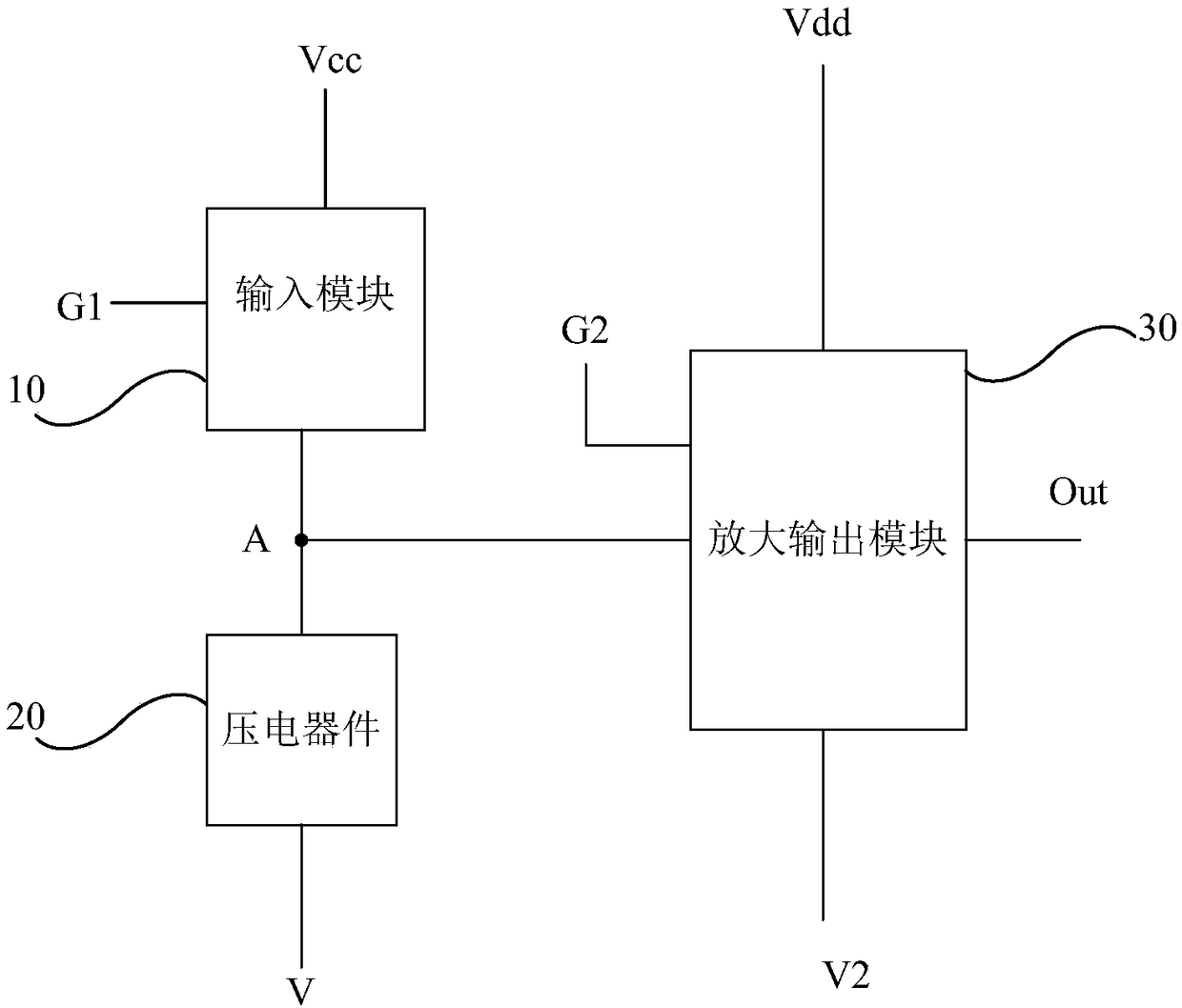
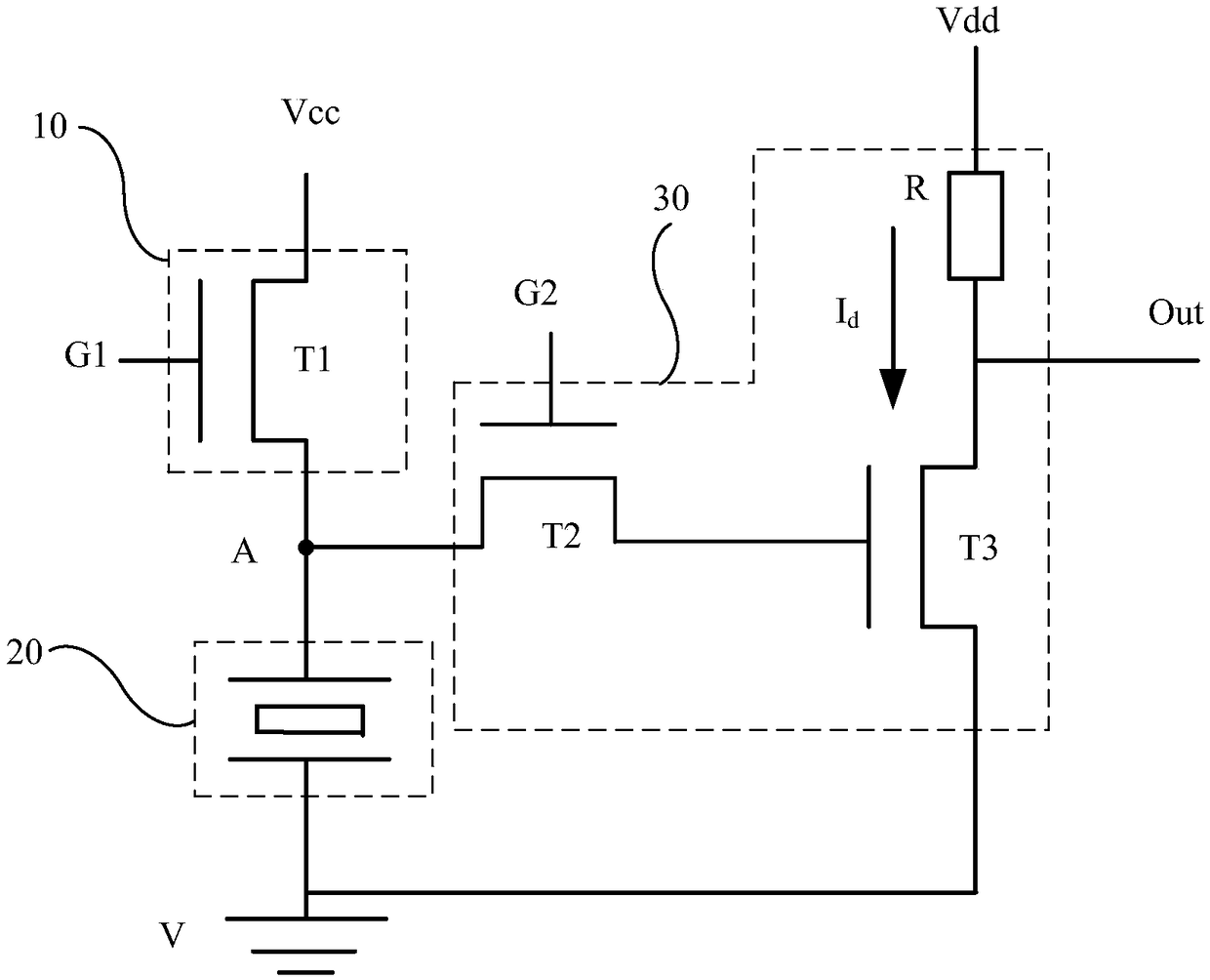
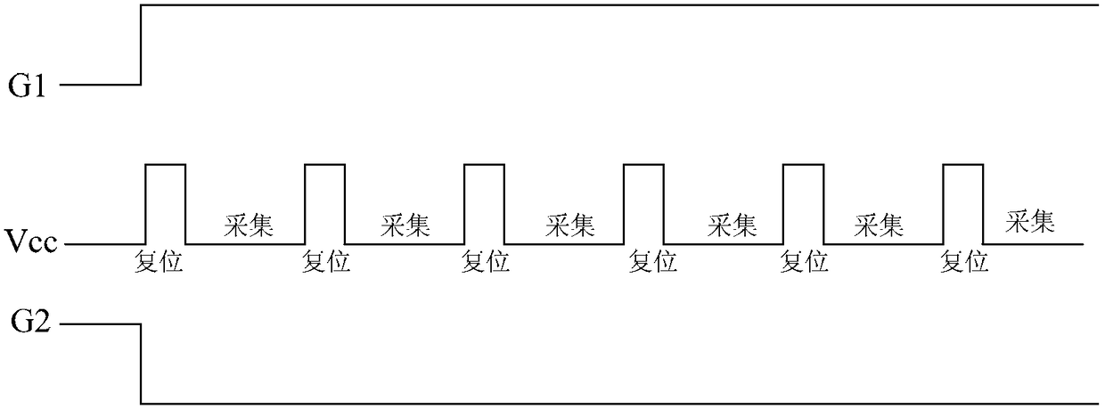
[0028] The present invention provides a time-division multiplexing piezoelectric circuit adopted in the piezoelectric device, through which the time-division multiplexing piezoelectric circuit can meet the pressure test and the control of ultrasonic generation in the piezoelectric device in different time periods; specifically, as figure 1 As shown, the time-division multiplexing piezoelectric circuit includes an input module 10 , a piezoelectric device 20 , an...


PUM


Abstract

Embodiments of the invention provide a time division multiplexing piezoelectric circuit and a control method thereof, and a piezoelectric apparatus, relates to the field of piezoelectric control, andavoids the problem of low integration degree of the piezoelectric apparatus in the prior art due to the requirement of setting of different driving circuits for pressure tests and ultrasonic generation. The division multiplexing piezoelectric circuit comprises a piezoelectric device, an input module and an amplification output module, the input module is connected with a first node, a signal inputterminal and a first control terminal and used for outputting signals of the signal input terminal to the first node, one terminal of the piezoelectric device is connected with the first node, the other terminal of the piezoelectric device is connected with a fixed voltage terminal to generate ultrasonic waves or perform resetting under the control of the first node or output piezoelectric signals generated by stress to the first node, and the amplification output module is connected with the first node, a second control terminal, a first voltage terminal, a second voltage terminal and a signal output terminal and used for amplifying the piezoelectric signals of the first node and outputting the amplified piezoelectric signals to the signal output terminal.

Description

technical field [0001] The invention relates to the field of piezoelectric control, in particular to a time-division multiplexing piezoelectric circuit, a control method thereof, and a piezoelectric device. Background technique [0002] Piezoelectric materials have attracted more and more attention in the field of electronics because of their own piezoelectric effect (electric field generated by mechanical deformation) and inverse piezoelectric effect (mechanical deformation generated by electric field). [0003] For example, in the prior art, a pressure test device is made according to the piezoelectric effect of the piezoelectric device (the electrical signals generated by the piezoelectric device are different if the pressure is different), and an ultrasonic generating device is made according to the inverse piezoelectric effect of the piezoelectric device (applied The electrical signal is different, and the piezoelectric device emits mechanical waves of different frequen...

Claims


Application Information

Patent Timeline
IPC IPC(8): H02N2/00H02N2/18B06B1/06B06B1/02G01L1/16
Inventor 曹学友王海生丁小梁刘英明郑智仁郭玉珍王鹏鹏韩艳玲刘伟张平
Owner BOE TECH GRP CO LTD
Learn More