Massive MIMO system configuration and verification method based on multiple sub-antenna arrays

An antenna array and system configuration technology, applied in the field of wireless transmission, can solve problems such as system performance degradation

Active Publication Date: 2018-08-17
GUANGZHOU UNIVERSITY
View PDF4 Cites 5 Cited by
  • Summary
  • Abstract
  • Description
  • Claims
  • Application Information

AI Technical Summary

Problems solved by technology

Compared with the fully connected array architecture, the massive MIMO system based on multiple sub-antenna array architectures can effectively reduce energy consumption and hardware implementation complexity. However

Method used


Image

  • Massive MIMO system configuration and verification method based on multiple sub-antenna arrays
  • Massive MIMO system configuration and verification method based on multiple sub-antenna arrays
  • Massive MIMO system configuration and verification method based on multiple sub-antenna arrays

Examples


Embodiment

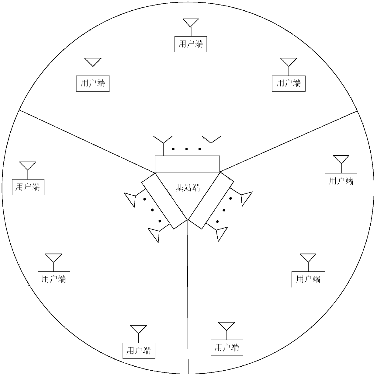
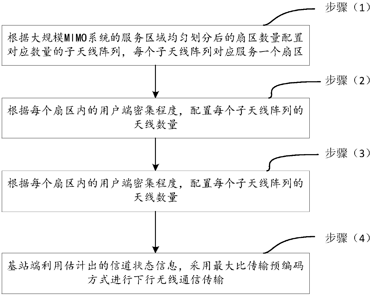
[0056] see Figure 1 to Figure 3 A method for configuring a massive MIMO system based on multiple sub-antenna arrays disclosed in this embodiment mainly includes the following steps (1) to (4):

[0057] Step (1): Configure a corresponding number of sub-antenna arrays according to the number of sectors after the service area of ​​the massive MIMO system is evenly divided, and each sub-antenna array corresponds to serve one sector.

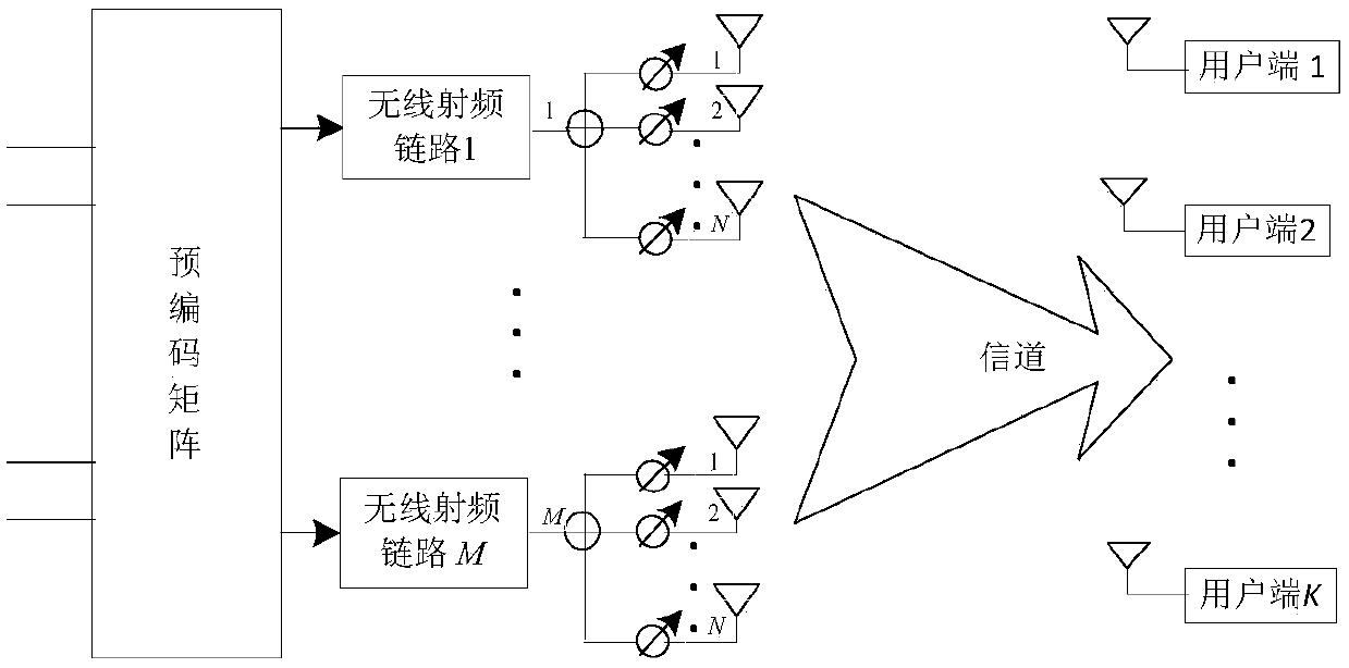
[0058] Step (2): Configure the number of antennas for each sub-antenna array according to the density of user terminals in each sector.

[0059] For steps (1) and (2) see Figure 1-Figure 2 , assuming that the service area of ​​the massive MIMO system is a cell, according to the service requirements in the cellular system, the cell is divided into M sectors, the number of sub-antenna arrays is equal to the number of sectors, and each sub-antenna array is required to serve a sector, Then, the number N of antennas of each sub-antenna array is determ...

example

[0080] In order to verify the spectral efficiency and performance of the massive MIMO system based on multiple sub-antenna arrays configured according to the above embodiment, and to compare it with the traditional MIMO system, a Monte Carlo experiment can be used to conduct a simulation test.

[0081] (1) The impact of the number of antennas on performance

[0082] see Figure 4 The radiation pattern of a uniform array antenna, given by Figure 4 It can be seen that for the case where the base station is configured with different numbers of antennas, for example, N t =10,N t =30,N t =100, as the number of antennas increases, the main lobe width of the array becomes very narrow, and the side lobes become smaller and smaller, and the attenuation speed becomes faster and faster, indicating that large-scale antenna arrays have stronger resolution capabilities . The number of antennas configured in the traditional MIMO system is relatively small. In contrast, the massive MIMO...


PUM


Abstract

The invention relates to a massive MIMO system configuration and verification method based on multiple sub-antenna arrays. The configuration method includes the following steps: configuring a corresponding number of sub-antenna arrays according to the number of sectors uniformly divided by a service area of a massive MIMO system, wherein each sub-antenna array serves one sector correspondingly; configuring the number of antennae of each sub-antenna array according to the density of clients in each sector; obtaining an observation matrix based on mutually orthogonal pilot training sequence information that is sent by all the clients in the service area and is received by a base station end, and the total number of the antennae of the base station end, and estimating channel state information in combination with the observation matrix; and enabling the base station end to perform downlink wireless communication transmission by using the estimated channel state information and a maximum ratio transmission precoding method. According to the scheme of the invention, the energy consumption and the complexity of hardware implementation can be effectively reduced, and the spectrum efficiency of the system can also be ensured.

Description

technical field [0001] The invention belongs to the technical field of wireless transmission, and in particular relates to a large-scale multiple input multiple output (Multiple Input Multiple Output, MIMO) system configuration and verification method based on multiple sub-antenna arrays. Background technique [0002] In recent years, with the widespread popularization and in-depth application of mobile communication, green communication will be an important development direction of the new generation of wireless communication. Effectively reducing the transmission power and hardware cost of the system under the same spectral efficiency is an effective way to realize green communication. one of the ways. Academia and industry are conducting research on future green wireless mobile communications in order to reduce the high hardware cost and astonishing power consumption of mobile communications. [0003] In the traditional all-digital MIMO (Multiple-Input Multiple-Output, r...

Claims


Application Information

Patent Timeline
IPC IPC(8): H04B7/0456H04B7/08H04L5/00H04L25/02H04L27/26
CPCH04B7/0456H04B7/0854H04L5/0048H04L25/0242H04L27/2692H04L27/2695Y02D30/70
Inventor 谭伟强范立生谢冬青谭伟杰夏隽娟蒲旭敏金石
Owner GUANGZHOU UNIVERSITY
Why Eureka
Try Eureka